8figure 2.1 • field wiring diagrams – Detroit Radiant Products Company SV Series User Manual
Page 8
SV
Series
8
Figure 2.1
•
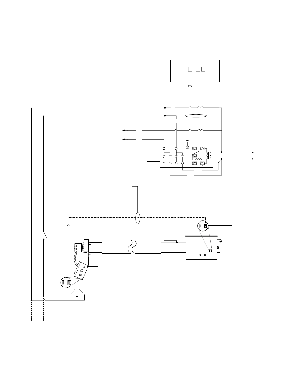
Field Wiring Diagrams
B. Low Voltage Thermostat Wiring (with optional R8285B transformer relay) - Up to Five Heaters per branch.
SV Series
Burner Box
BK
W
Low voltage wire (14 ga. multistrand
required) must be installed a
minimum of 18 inches from the
reflector and outside of the
clearance to combustibles zone.
Up to four
additional heaters
1/4” female
spade terminals
(as supplied).
Power Box
Assembly
1/4” female spade
terminals (as supplied).
To heater branch #2
(Up to five heaters per branch)
To heater branch #1
N
L1
120VAC
Low Voltage Thermostat
C W R
14 ga. multistrand
low voltage wire
(as supplied)
Common required for thermostats
that require constant power.
N
L1
120V
R8285B Transformer Relay (optional)
Required when wiring line voltage
heaters to any low voltage thermostat.
POLE
#1
POLE
#2
W
R
G
Y
C
Coil
W
B
R/Y
R
BK
W
W
V
2.0
Installation
•
Wiring