Caution, Warning – Detroit Radiant Products Company DES3 Series User Manual
Page 32
CAUTION
!
WARNING
!
32
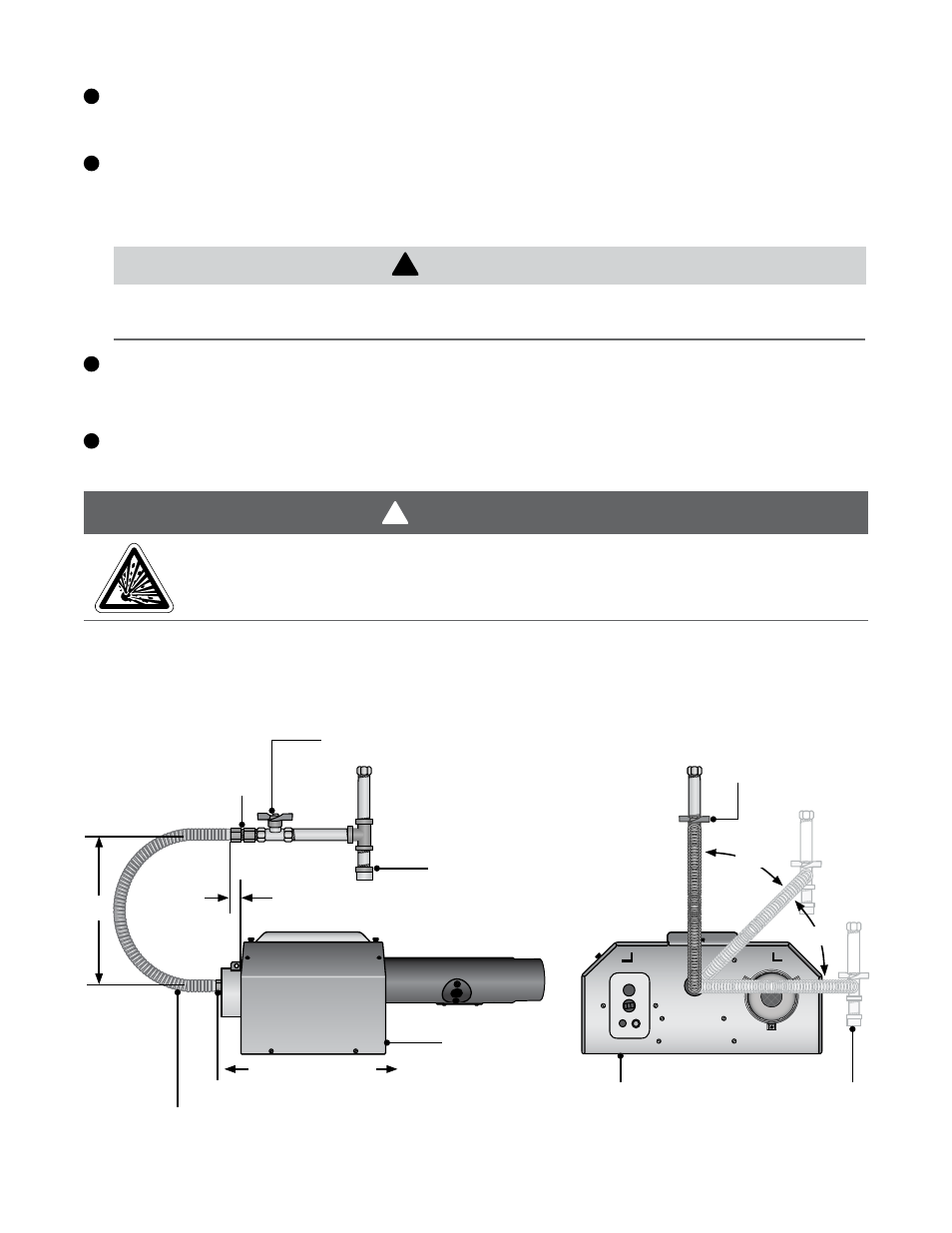
Form the stainless steel flexible connector (supplied) into a smooth C-shape allowing 12 in. between
the flexible connector’s end nuts (see figure 3.30).
Attach a ball valve (field supplied) to the gas supply pipe. Apply pipe compound to NPT adapter
threads to seal the joint. Use only a pipe compound resistant to LP.
NOTE: Provide a 1/8 in. NPT plugged tapping accessible for test gauge connection immediately
upstream of gas connection to the heater (typically provided on ball valve).
Attach the flexible connector to the adapter and burner control box inlet. Seal the joints.
NOTE: Excessive torque on the manifold may misalign the orifice. Always use two wrenches to
tighten mating pipe connections.
Final assembly must be tested for gas leaks according to NFPA 54 and all local codes and/or
Standards.
3.0
Installation
•
Gas Supply
Figure 3.30
•
Gas Connection (Flexible Gas
Connection shown)
•
Side View
12”
When using a stainless steel flexible connector,
do not attach the connector nuts directly to the gas
pipe supply. Connector nuts must be installed to an approved adapter.
Ball Valve / Inlet Tap
(Field Supplied)
Stainless Steel Gas Connector,
formed into smooth C-Shape
Adapter
Figure 3.31
•
Gas Connection (Flexible Gas
Connection shown)
•
End View
45°
Remove cap to clean
sediment trap.
45°
Testing for gas leaks with an open flame or other sources of ignition may lead to a fire or
explosion and cause serious injury or death. Test in accordance with NFPA or local codes.
2 in. max displacement
Drip Leg/
Sediment Trap
Heater Movement
Adapter
Burner Control Box
End View
Burner
Control Box
Side View
Ball Valve / Inlet Tap
(Field Supplied)
NOTE: Do not exceed 14 Inches W.C. to the appliance.
2
3
4
5