Baffle assembly and placement – Detroit Radiant Products Company DES3 Series User Manual
Page 22
Baffle keyhole
Baffle tabs
Completed connection
2
22
3.0
Installation
•
Baffle Assembly and Placement
Different models and inputs utilize specific baffle lengths. Remove all enclosed baffle sections from box
and retain with applicable heater. Reference shipping label for proper baffle size.
To assemble the baffles: NOTE: Baffles may be inserted into the tube while being assembled.
Determine the number of baffles needed for your model number.
Remove one 36 in. baffle section
if heater is fitted with an elbow (P/N: E6) or U-bend (P/N: TF1B) accessory.
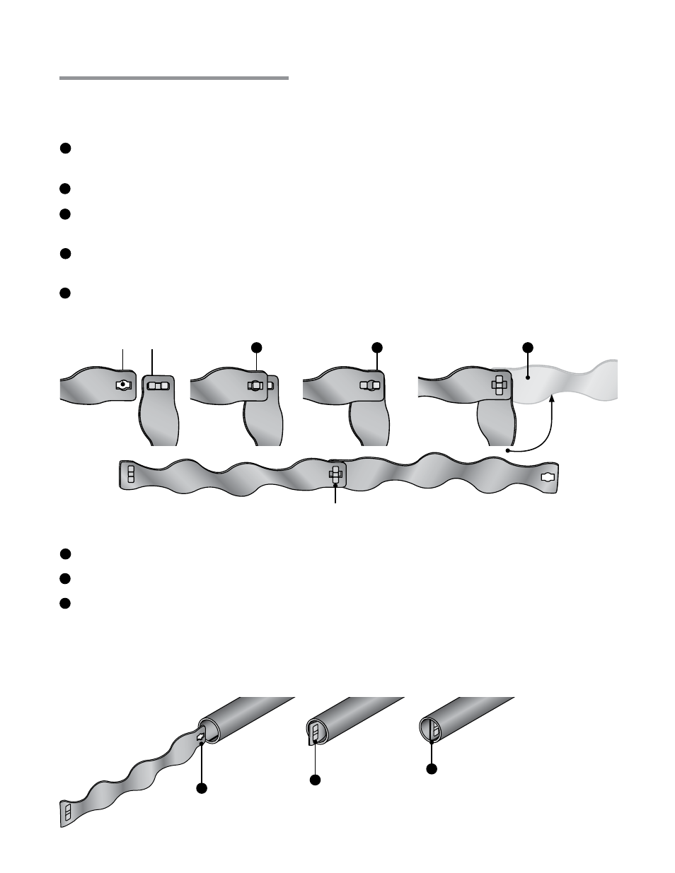
Orient the baffle tabs at a 90° angle to the baffle keyhole (see figure 3.19).
Insert one baffle tab into keyhole and slide completely to one side until both baffle tabs appear in
the keyhole.
Adjust the tabs to the center of the keyhole and rotate the baffle 90 degrees to lock the baffle
sections together.
Repeat this process with all remaining baffle sections to complete assembly.
Figure 3.19
•
Assembling the Baffles
Figure 3.20
•
Inserting the Baffles
To insert the baffles:
Insert baffles with the keyhole end first.
Rotate baffle assembly so that it is in the
vertical position.
Slide baffle assembly into the last radiant tube section, furthest from the burner control box.
NOTE:
Baffle assemblies longer than 10 ft. will continue to be fed into next tube section.
When the heater is
configured with a ‘U’ or ‘L’ shaped accessory fitting It may be necessary to cut the baffle in two
sections. In this case, place as much baffle as possible downstream of the fitting and the remainder
just before the fitting.
IMPORTANT: Baffle assembly
must be flush with the end of
the last tube section and in the
vertical position.
Baffle Assembly and Placement
1
2
3
4
5
3
4
1
2
3
1
2
3