Final heater assembly – Detroit Radiant Products Company DES3 Series User Manual
Page 23
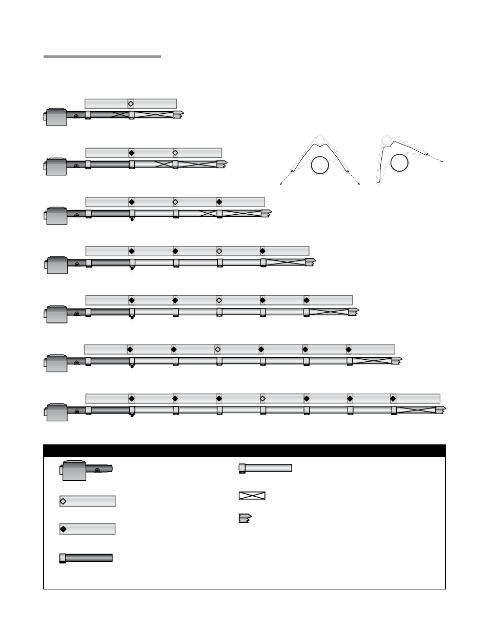
Chart 3.6
Tube Installation Sequence, Baffle Location and Secured Joints for Reflectors
30 Foot
40 Foot
*
*
*
*
*
Burner Control Box
w/16 in. Burner Tube
Key
Expansion Joint on
Reflectors
Secured Joint on
Reflectors
Primary Combustion
Chamber with Clamp
Radiant Tube
Exchanger with Clamp
Baffle Location
Secure vent material to exchanger with three #8
sheet metal screws. Seal with high temperature
silicone sealant. Do not use tube clamp.
23
20 Foot
Final Heater Assembly
3.0
Installation
•
Final Heater Assembly
*
A secondary combustion chamber is installed as the
second tube downstream from the burner control box on
150,000 to 200,000 BTU/h models. Refer to the Series
Insert Manual for installation requirements.
50 Foot
60 Foot
70 Foot
80 Foot
Stainless steel clamp on 150,000 to 175,000 BTU/h
models (P/N: TP-220).
Stainless steel clamp on 150,000 to 200,000 BTU/h
models (P/N: TP-220).
Stainless steel clamp on 150,000 to 200,000 BTU/h
models (P/N: TP-220).
Stainless steel clamp on 150,000 to 200,000 BTU/h
models (P/N: TP-220).
Stainless steel clamp on 150,000 to 200,000 BTU/h
models (P/N: TP-220).
NOTE: When securing joints on reflectors which
are rotated on an angle from horizontal, secure
joint only on top side of reflector to allow for
sufficient heater expansion and contraction.
1 to 45° Mounting Angle
0° Mounting Angle