Micromod RetroPAK: MOD 30 Installation Manual User Manual
Page 29
MOD 30ML Replacement for MOD 30 Instruments
REPLACEMENT PROCEDURE
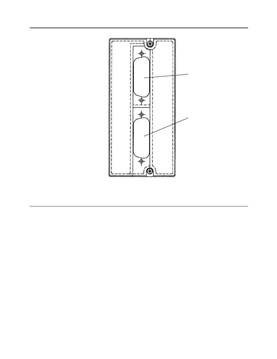
Figure 3-4. Cable Connector Locations In Back Cover
J1
J2
3.6.2
Electrical Connections
The required power, ICN communication, and I/O signal connections to the replacement
instrument are made via the cables which are installed as part of the mounting procedure.
! CAUTION
If I/O module location S7, S8, S9, or S10 is used for a digital input or
output, the negative terminal of the alternate analog signal which can use
the location must be grounded to the negative power supply terminal at
the termination panel, and the positive terminal of the analog signal must
be open circuited.
The negative analog and power terminals are identified in Figure 3-5. The required
connections are as follows:
• To use module location S7 for a digital signal, ground Analog Input 5 negative.
• To use module location S8 for a digital signal, ground Analog Input 6 negative.
• To use module location S9 for a digital signal, ground Analog Input 3 negative.
• To use module location S10 for a digital signal, ground Analog Input 4 negative.
*
NOTE:
Before putting the instrument into operation, it must be configured using either
the front panel keys or the 2006S Application Builder software. See Section
1.1.2 for related documents.
25