Liquid Controls SP2900 User Manual
Page 19
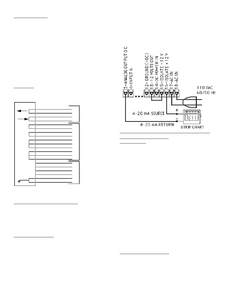
The unit can supply the 24VDC to power the current loop.
(Connect Pin 15 to Pin 13. Pin 16 is now + 24VDC with
respect to Pin 12). With Pin 15 connected to Pin 13,
connect Pin 16 to the + DC side of the external device and
connect Pin 3 to - DC side of the external device.
OPTIONAL 16-POINT LINEARIZATION OF
VARIABLE K-FACTOR
DESCRIPTION
The 16 point K-Factor option allows the user to dial in from
3 to 16 different frequency points (inputs per second) and
different K-Factor dividers from 0.0001 to 99999999 for
each of these frequencies.
The 16 point unit determines the incoming frequency and
calculates a K-Factor line slope from the two closest data
points that had been entered. The “specific K-Factor” is
then proportionally interpolated using 8-position floating
math. This K-Factor is applied to all inputs until the next
frequency calculation, usually 1 second later. If a “0”
frequency is entered into “point 1”, the “point 1” K-Factor
will be applied to all inputs received before the first fre-
quency calculation.
The rate can be displayed in 3 ways: “SECONDS _”,
“MINUTES _”, “HOURS _”, or “TEST _”. If “SECONDS” is
selected, the unit displays the “base rate” calculated from
the incoming frequency and the “specific K-Factor”. If
“MINUTES _” is selected, the rate displayed is 60 times the
“base” rate. If “HOURS _” is selected, the rate displayed is
3600 times the base rate.
POINT DATA FORMATTING
Each Frequency/K-Factor data entry is assigned a point
number. Any point number may be selected to view and/or
change the Frequency/K-Factor data as long as the fre-
quencies of the ascending frequencies. “BAD FREQ” will
flash when exiting the set up mode if there is a sequence
error. The unit will then display the sequence error point #
so that corrections can be made.
RS422 WIRING
The unit RS422 option has a subminiature D 37 pin female
connector and is wired as a DCE (Data Communication
Equipment) device. It is designed to be connected to a DTE
(Data Terminal Equipment) device. If it must be connected
to a DCE device, it will be necessary to cross wires 4 and 6
as well as 22 and 24 at one end of the connector harness.
The unit requires only 5 wires for RS422 communications;
Pin 22 [Receive Data + (A)], Pin 4 [Receive Data - (B)], Pin
24 [Transmit Data + (A)], Pin 6 [Transmit Data - (B)], Pin 20
(Sig. Ground). The following groups of pins have been
jumped internally to echo back the signals: (7, 9), (25, 27),
(11, 12, 13), (29, 30, 31). Signal ground (Pins 19, 20) must
be connected to provide a common reference
HOOKUP
RS422/Strobe (SUB-D 37 Pin Conn.)
.
STROBE WIRING FOR RS422
The 3 data lines to generate the request code (DL1: Pin 21,
DL2: Pin 14, DL4: Pin10) must be set and remain constant
while the positive strobe of at least 12 milliseconds is given
on strobe input (Pin 3). Data is transmitted in RS422 serial
format on Transmit Data Lines (Pin 6-24).
ANALOG OUTPUT
When used with a digital input, the Analog Output module
is separate and plugs on just to the right of the input
module. When used with analog input (7A to 7E), the
Analog Output logic is combined on one analog input/
output module. (The white wire from the module plugs onto
pin J2-6). The output on external pin 3 is a 4mA to 20 mA
output corresponding to the selected rate readings. A
sinking driver generates a linear current across recorder,
PLC, computer, external meter. In the program set up
mode the user is prompted to “SET LOW” (4mA rate) and
“SET HIGH” (20mA rate).
17
22 RD+ (A)
4 RD- (B)
24 TD+ (A)
6 TD- (B)
7 RTS+
9 CTS+
25 RTS-
27 CTS-
11 DSR+
12 DTR+
13 RLSD+
29 DSR-
30 DTR-
31 RLSD-
21 DL 1
14 DL 2
10 DL 4
3 STROBE
19 SIG. GROUND
20 SIG. GROUND
RS 422
DATA
OPT
INTERFACE
STROBE
DATA