Liquid Controls SP2900 User Manual
Page 18
Following are two examples of requests and responses.
Transmit from
Receive from
Terminal
Unit
(S) = Space
Example A:
D13(S)
Device #13
[Unit #13 Activated]
PA(S)76546(S)PA(S)
PA 76546 PA
KC(S)1575(S)KC(S)
KC 1575 KC
RC(ENTER)
RC
[Unit presets and counter K-Factor are set, counter is reset]
76546
1575
Example B:
D7(S)
Device #7
[Unit #7 Activated]
PA(S)12347(S)PA(S)
PA12347 PA
RC(S)456789(S)DC(S)
RC 456789 DC
RT(S)376(S)DT(ENTER)
RT 376 DT
[Unit preset, counter and total count are set]
12347
456789
376
STROBE ADDRESS OPERATION
Another method of reading the status of a unit with either a
RS232 or RS422 option is by means of a separate strobe
address and a 3 bit data request code. Use of the strobe
address method does not allow the input of new set points
but theoretically hundreds of units could be linked together
to transmit the data in the unit over the serial transmit line
in the standard RS232 or RS422 format. The unit could be
assigned any code number other than “00”.
The 3 bit data request code would be latched in at the
positive edge of a 3 to 30 VDC strobe input that remain
high a minimum of 25 milliseconds. Requests are proc-
essed on a nonpriority basis. Normally data will begin to be
transmitted from the unit over the RS232 or RS422 serial
transmit line within 5 msc unless interrupted by a keypad
entry or other signal input.
No other unit should be brought on line until data requested
has been transmitted.
STROBE INPUT ELECTRICAL
REQUIREMENTS
Both the RS232 and RS422 interface option cards have
inputs that allow data to be requested over a separated
strobe input and a 3-bit data request code input. Any
number of the 3 data request code lines can be linked in
parallel as long as the source can drive the combined load
of all inputs linked together (1.5K Ohm divided by the total
number linked together). Data is transmitted over the serial
lines using standard RS232 or RS422 characteristics.
Strobe and data ground as reference:
STROBE INPUT LEVELS
0 or low: Open or 0 to 1VDC
1 or high: 3 to 30 VDC
Impedance: 1.5K Ohm
STROBE INPUT CODES (Octal Code)
0: PA (Preset A request)
1: PB (Preset B request)
2: KC (K-Factor or counter request)
3: KR (K-Factor of rate request)
4: DC (Display of count request)
5: DT (Display of grand total request)
6: DR (Display of rate request)
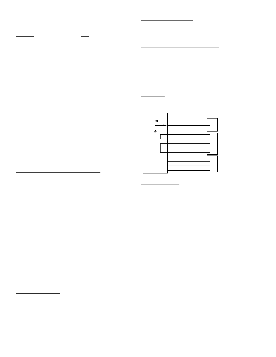
HOOKUP
RS232/STROBE
(SUB-D 25 PIN CONN.)
RS232 WIRING
The unit requires only three wires for RS232 communica-
tion: Pin 7 (Signal Ground), Pin 2 (Receive Data), Pin 3
(Transmit Data). Pin 4 (Request to Send) are jumped
internally to echo back the signals. Pins 6 (Data Set
Ready), 8 (Received Line Signal Detector) and 20 (Data
Terminal Ready) are also jumped internally to echo back
any signal.
The unit RS232 option has a subminiature D25 pin female
connector and is wired as a DCE (Data Communications
Equipment) device. If it is connected to a DTE (Data
Terminal Equipment) device, the interconnect cable should
have wires 2 and 3 connected straight to the same pins on
each end. If it is connected to another DCE device, Pins 2
and 3 must be crossed so that the wire to Pin 2 on one end
goes to Pin 3 on the other end and Pin 3 on one end goes
to Pin 2 on the other end.
STROBE WIRING FOR RS232
The 3 data lines to generate the request code (DL 1: Pin 9,
DL 2: Pin 10, 2: DL 4 Pin 11) must be set and remain
constant while the positive strobe of at least 25 millisec-
onds is given on the strobe input (Pin 18). Data is transmit-
ted in RS232 serial format on Transmit Data Line (Pin 3).
16
RS232
DATA
OPT.
INTERFACE
STROBE
DATA
RD
TD
SIG. GROUND
RTS
CTS
DSR
RLSD
DTR
DL1
DL2
DL4
STROBE
2
3
7
4
5
6
8
20
9
10
11
18