Liquid Controls SP2900 User Manual
Page 11
SPECIFICATIONS
Display
8 Digit, .55” Segment, Red Orange, LED.
Input Power
A: 110 VAC
±
15% or 12 to 27 VDC
B: 220 VAC
±
15% or 12 to 27 VDC
Current
Maximum 280 mA DC or 5.3 VA at rated AC voltage.
Output Power
(On AC powered units only): +12 VDC at 100mA. Separate
isolated 12 VDC at 100mA to allow +12 VDC or +12 VDC
regulated
±
5% worst case.
Memory
EEPROM stores all program and count data for minimum of
10 years if power is lost.
Pulse Inputs
Standard, High impedance pulse input. Open or 0 to 1 VDC
(low) 3 to 30 VDC (high) 10K Ohm impedance 20 KHz max.
input speed (min. on/off 25 usec.).
Analog Inputs
The current loop or voltage input is converted to a highly
linear 0 to 10KHz frequency. This frequency can then be
scaled by the 8 digit K - Factors to count or display rate in
separate engineering units.
Accuracy over full temperature range:
Zero error:
±
0.175% full scale max.
Overall error:
±
0.5% full scale max.
Reset
Front push button: “CLR” resets displayed number and
control output.
Remote: 3 to 30 VDC positive edge resets batch counter
and control output.
Impedance: 10K to ground (-DC)
Minimum pulse: 5 msec
Temperature
Operating: +32ºF (0ºC) to +130ºF (+54ºC)
Storage: -40ºF (-40ºC) to+200ºF (+93ºC)
Factored Output
The unit gives one pulse out for each factored count. Open
collector sinks 30 VDC maximum to 1 volt maximum at
100mA maximum. Output speed is user selectable (see
Table below). An internal buffer holds up to 10,000 pulses
for output at the selected frequency before “DATALOST”
flashes, indicating pulses are lost. If factored rate exceeds
7 digits, “RFF...” flashes. These alarms indicated that
speed has been exceeded.
Speed (Hz)
10
200
2000
20000
Min. on/off (msec)
47.5
2.0
0.2
0.013
Control Outputs
(Each of two outputs)
1) NPN Transistor Version: (Optional)
Open collector sinks max. 250mA from 30
VDC when active. (When relay is used, 10
VDC is provided at transistor outputs through
relay coil. If greater than 2mA is used, relay
will remain energized. Applying greater than
10 VDC may destroy unit. Transistor will sink
100mA in “ON” state).
2.) SPDT Relay Version:
10A 120/240 VAC or 28 VDC (Standard)
Analog Output
Digital or analog inputs (except square law) can be ordered
with a 4mA to 20mA output of the rate or total reading.
User keys in the 4mA and 20mA settings at set-up. A
sinking driver generates a corresponding linear current
through the external devices, updating with each update of
the rate or total. Accuracy is
±
100 uA worst case. Compli-
ance voltage must be 3 to 24 VDC, non-inductive. (The
unit can provide the DC source as long as the drop across
any device being driven does not exceed 21 V).
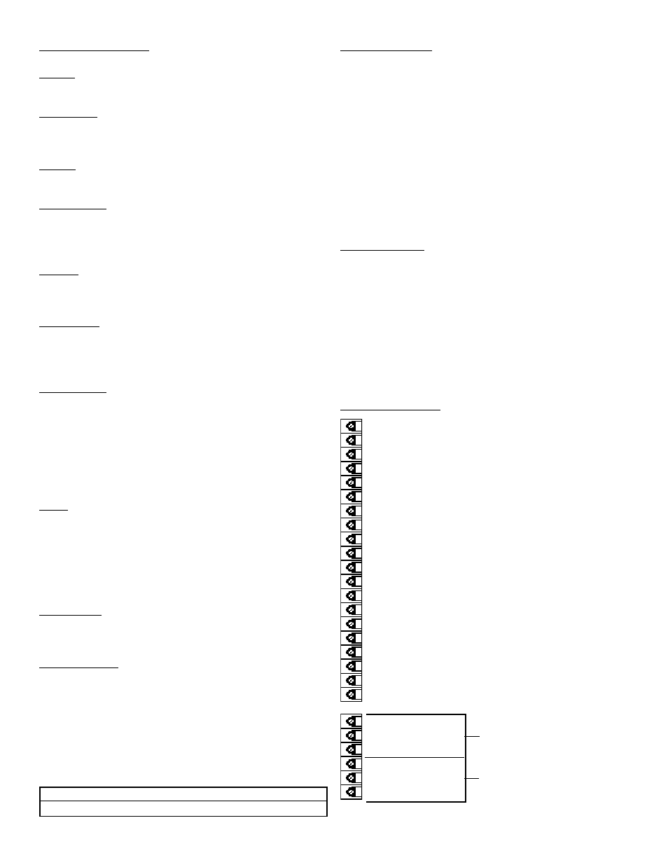
TERMINATIONS
1- NOT USED
2- SCALED OUTPUT O.C.
3- ANALOG OUTPUT (SINK)
4- INPUT A (PULSE/ANALOG)
5- RESET INPUT
6- NOT USED
7- NOT USED
8- NOT USED
9- NOT USED
10- NOT USED
11- GROUND (-DC)
12- GROUND (-DC) INPUT COMMON
13- +12 VDC OUT
14- +DC POWER IN
15- ISOLATED -12VDC
16- ISOLATED +12VDC
17- AC IN
18- AC IN
19- PRESET B OPEN COLLECTOR
20- PRESET A OPEN COLLECTOR
R1- N.O
R2- N.C.
A
R3- COMMON
R4- N.O
R5- N.C.
B
R6- COMMON
9