Appendix – Liquid Controls HML210 IOM - LCMag User Manual
Page 41
HML 210
41
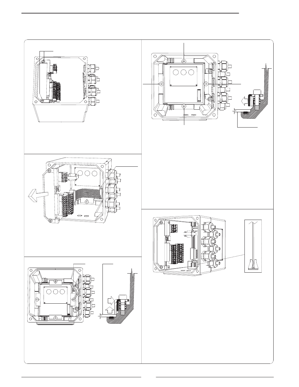
Fixing screw
of board
Unscrew the screw as indicated in pic. 1
Lift the board, remove the flat cable
from the display (pic. 2) and extract
completely the board from the box
definitely the board from the box
Pic.2
4 mm hex spanner
Display
Partially unscrew the screw fixing the
display to allow the angular shift and
extraction of the display
N.B.: Do not unscrew entirely the screw
Take off the
flat cable
1
2
3
4
Display
Rotate the display to the desired location,
verify the correct set of the seal, the cleaning
of the contact surfaces it set the display
housing.
Place the fixing angles in the suitable
positions (pic. 5) and screw down firmly until
they make contact with the display housing.
Screw up tightly the 4 screws (1, 2, 3, 4)
indicated in pic. 4
Pic.6
Pic.4
Pic.7
Note: the display is rotable ONLY in the aluminum IP67 version.
APPENDIX
DISPLAY ROTATION PROCEDURE
Pic.3
Restore the flat cable connection to the display
Verify the board is set correctly in the fixing
clip (pic. 7)
Fix the board to the box to complete the
assembly process.
Pic.5
Pic.1