Liquid Controls HML210 IOM - LCMag User Manual
Page 32
HML 210
32
10
20
30
40
50
60
0
0
2
4
6
8
10
12
14
16
18
20
22
MFSLN: 0,0s
MFFLN: 0,0s
FLOW RATE
MEASURE
FILTERS
>>>>
>>>>
10
20
30
40
50
60
0
0
2
4
6
8
10
12
14
16
18
20
22
10
20
30
40
50
60
0
0
2
4
6
8
10
12
14
16
18
20
22
1,0sec.
1,0sec.
1,0sec.
1,0sec.
1,0sec.
5,0sec.
IN
OUT
MFSLN: 5,0s
MFFLN: 1,0s
FLOW RATE
MEASURE
FILTERS
>>>>
>>>>
IN
OUT
MFSLN: 5,0s
MFFLN: 0,0s
FLOW RATE
MEASURE
FILTERS
>>>>
>>>>
IN
OUT
FL
O
W
R
A
TE
(%
)
TIME (Sec)
TIME (Sec)
FL
O
W
R
A
TE
(%
)
TIME (Sec)
FL
O
W
R
A
TE
(%
)
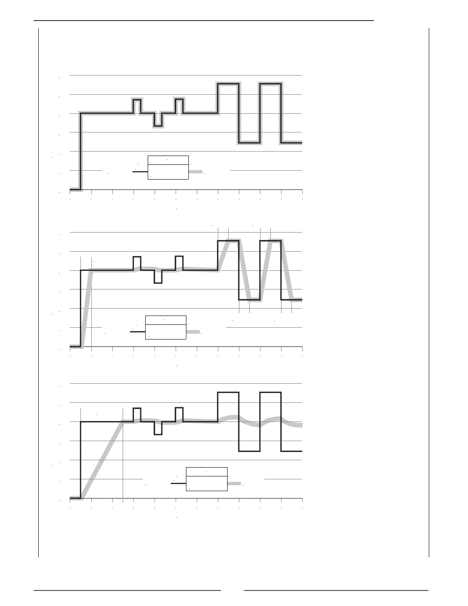
The following diagrams show the response of the instrument for a flow rate variation from 0 to 100%
of full scale set using different settings of filters.
Both filters to zero
(batching setup): the
measure
quickly
follows the flow rate
behaviour
Both filters are used
(Smart mode): prompt
reaction to quick flow
variation (based on
the
MFFLN
value);
smoothing
the
measure result to slow
flow variations (based
on MFSLN value)
Only M. filter (MFSLN)
is used (regulation
and
flow
measure
setup): smoothing the
measure result (based
on MFSLN value) in
reaction to quick and
slow flow variation
(MFFLN
does
not
work).