Converter access flags and led interpretation – Liquid Controls HML210 IOM - LCMag User Manual
Page 17
HML 210
17
M1
M3
1
2 3 4 5 6 7 8 9 10
11 12 13 14 15 16 17 18 19 20
LOCK
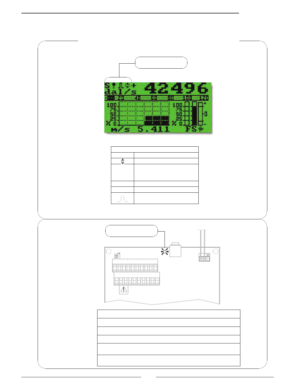
CONVERTER ACCESS
FLAGS AND LED INTERPRETATION
FLAGS INTERPRETATION
FLAG
DESCRIPTION
Alarm max/min activated
!
- Interruption coils circuit
- Segnal error
- Empty pipe
C
Calibration running
S
Simulation
Pulse output saturation
(reduce TIME PULSE )
LED
LED INTERPRETATION
PERMANENT LIGHT: initialization
FLASHING LIGHT (1 sec.): normal function
FLASHING LIGHT (<1 sec.): alarm on
The LED signals the real alarm status only if the display visualizes
one of the visualization pages
ATTENTION: The LED is not visible in the panel version of the
converter
FLAGS
See also other documents in the category Liquid Controls Equipment:
- Gear Plate Selection Guide (24 pages)
- MS Meters (40 pages)
- MA4 Meter (32 pages)
- M-MA Meters (28 pages)
- HMS3700 & HMS3770 Insertion Sensors LC Mag Insertion (8 pages)
- HMS501, HMS600, HMS1000, HMS2400, HMS2500, and HMS5000 LC Mag IOM (8 pages)
- CIM100 (16 pages)
- Rate of Flow (4 pages)
- HML4-F1 - LCMag (40 pages)
- LCRII Install E3650-E3651 Series (40 pages)
- LCR-II Setup & Operation (60 pages)
- LCRII Menu Map (2 pages)
- LCR-II - Quick Reference (2 pages)
- LCR Install (24 pages)
- LCR Setup & Operation (60 pages)
- LCR 600 Install (36 pages)
- LCR600 Wiring Schematic (1 page)
- LCR 600 Setup & Op (68 pages)
- LCR 600 - Quick Reference (2 pages)
- FlightConnect 600 (52 pages)
- FlightConnect 600 QR (2 pages)
- LCR-II Installation E3655-E3656 (36 pages)
- LCRII E3651-E3656 Wiring Schematic (1 page)
- DMS Installation (20 pages)
- DMS Setup (84 pages)
- DMS Delivery (52 pages)
- DMS i1000 Quick Reference - DMS Delivery (2 pages)
- DMS Office (52 pages)
- DMS i1000 EZConnect Operators (36 pages)
- DMS i1000 Quick Reference - EZConnect (2 pages)
- EZConnect Office (44 pages)
- FlightConnect Office (36 pages)
- FlightConnect Setup Guide (8 pages)
- DB Manager (20 pages)
- POD (16 pages)
- Dual Meter Multiplexer (8 pages)
- Differential Pressure Transducer (12 pages)
- XL LED Display E1615_E1616_E1617_E1618 (20 pages)
- SCAMP (20 pages)
- WinHost Operation (44 pages)
- SP714-S2i (12 pages)
- HML110 IOM (31 pages)
- Sponsler T675 - Cryogenic System Register (54 pages)
- Sponsler IT400 Electronic Register (40 pages)