Power installation, Connecting power to the dms – Liquid Controls DMS Installation User Manual
Page 17
17
PoWer InsTallaTIon
Do not apply power to the DMS Module until the LectroCount
Register has been rewired for RS-485 communication. Refer to
page 13 for instructions on rewiring the LectroCount Register
for RS-485 communictaion. Failure to rewire the LectroCount
register prior ro applying power may result in damage to the
DMS Module.
Connecting Power to the dMs
Typically, the voltage source of the DMS is the accessory
panel. Powered by the accessory panel, the DMS has
power only when the ignition switch is in the ON or
ACCESSORY position. The DMS receives no power
when the ignition is OFF eliminating any drain the DMS
might have on the battery. The DMS is also powered
down when the engine is cranking in order to prevent
damage caused by voltage spikes or electrical noise that
can occur when the starter is engaged.
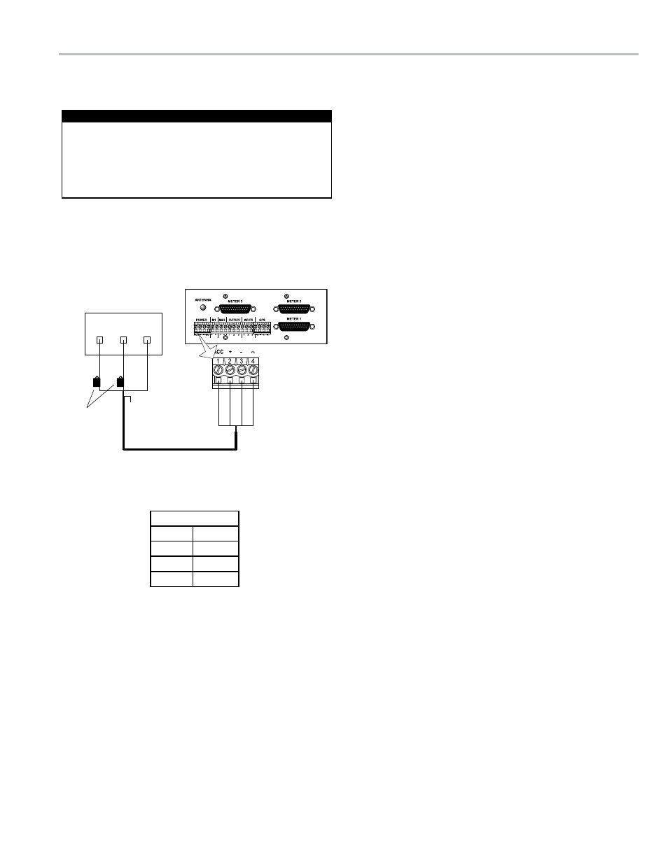
The DMS power cable (Part No. 81973) is a three wire
with shield cable with two in-line fuses installed on the
red and white wires. The end with the two in-line fuses
is wired to the truck’s power source. The other end is
connected to the left-most terminal connector on the rear
panel of the DMS Module.
To connect the dMs to the truck’s power:
1. Locate a +12 VDC switched accessory source, and
connect the white wire to the panel.
2. Locate a +12 VDC battery source, and connect the red
wire.
3. Connect the black wire to a good ground.
4. Route the cable to the rear of the DMS Module. Ensure
that the cable is protected.
5. Remove the left-most terminal connector from the rear of
the DMS.
6. Connect the white wire to pin 1.
7. Connect the red wire to pin 2.
8. Connect the black wire to pin 3.
9. Connect the shield wire to pin 4.
10. Reattach the terminal connector to the DMS
Vehicle Accessory Panel
+12VDC
Accessory
Ground
Shield
In-Line Fuses
(7.5A)
White
White
Re
d
Re
d
Blac
k
Blac
k
Shiel
d
+12VDC
Battery
DMS Power Connection
Before Powering Up the DMS
DMS Terminal Pins
White
Pin 1
Red
Pin 2
Black
Pin 3
Shield
Pin 4