Data conections, Dms & lectrocount registers – Liquid Controls DMS Installation User Manual
Page 13
13
dMs & lectroCount registers
Connecting the DMS and a LectroCount register(s)
together for data communication requires some minor
rewiring on the LectroCount 81920 CPU board. Two
wires from the 40' data cable (PN 81513040) must be
moved to different terminals. The connector at the other
end of the data cable must be plugged into the specified
DMS port. The LectroCount 84040 CPU requires no
modification to communicate with the DMS.
The DMS provides female communication ports for three
LectroCount registers with 81513040 data cables.
daTa ConneCTIon To The dMs
Single Meter Systems
To install data communication for a single meter system,
plug the DB-25 connector of the LectroCount data cable
into the DMS port labeled “METER 1”.
Multiple Meter Systems
To install data communication for a multiple meter
systems, plug the DB-25 connector of each LectroCount
data cable into its respective DMS port: “METER 1”,
“METER 2”, or “METER 3”.
WIrInG leCTroCounT reGIsTers for dMs
CoMMunICaTIon
When connecting a DMS to a single or multiple meter
system with LectroCount registers with 81920 CPU
boards, they must be configured to communicate via
RS-485. LectroCount registers with 84040 CPU boards
do not require any configuration to communicate via RS-
485.
To configure LectroCount LCR-II registers to RS-
485:
1. Shut off power to the registers before moving any wires
or jumpers.
2. Open the register(s).
3. On terminal block J3, remove the red wire from pin 46
and the violet wire from pin 48.
4. On terminal block J2, attach the violet wire to pin 25 and
the red wire to pin 24.
5. Move the J10 jumper position from 232 to 485. Newer
registers may be labeled P, for RS-485, and T, for RS-
232.
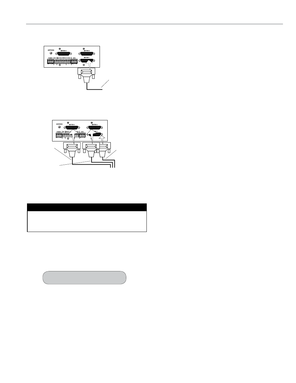
daTa ConeCTIons
Electronic Register 1 Connection
Electronic Register 2 and 3 Connections
Register 1
Data Cable 40’
PN 81513040
Register 3
Data Cable 40’
PN 81513040
Register 2
Data Cable 40’
PN 81513040
Register Data Cable 40’
PN 81513040
Do not apply power to the DMS Module until the LectroCount
Register has been rewired for RS-485 communication.
Before Powering Up the DMS
See page 14 for diagrams.