Laurel Electronics LAUREATE SERIES 2 SERIAL INPUT METER & REMOTE DISPLAY User Manual
Page 18
18
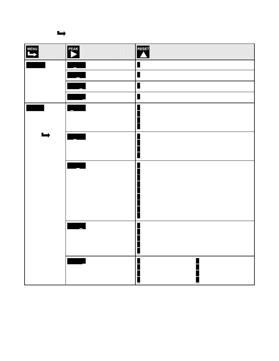
KEYSTROKES FOR SETUP
If the MENU
key does not work, see Section 9 “Enabling & Locking Out Menu Items.”
Press
Menu
Press Digit
Select Key
Press Value Select
Key
0000
Setpoint 1:
3
Must be set to Item #3.
0000
Setpoint 2:
3
Must be set to Item #3.
0000
Setpoint 3:
3
Must be set to Item #3.
SourcE
Source to com-
pare to setpoint
0000
Setpoint 4:
3
Must be set to Item #3.
00000
Relay state when alarm is
active
0
Relay 1 on
Relay 2 on
1
Relay 1 off
Relay 2 on
2
Relay 1 on
Relay 2 off
3
Relay 1 off
Relay 2 off
00000
Alarm latching or non-
latching (auto reset)
(see Glossary)
0
AL1 auto reset
AL2 auto reset
1
AL1 latching
AL2 auto reset
2
AL1 auto reset
AL2 latching
3
AL1 latching
AL2 latching
00000
Alarm operates at and
above setpoint (active
high) or at and below
setpoint (active low).
(see Glossary)
0
AL1 active high
AL2 active high
1
AL1 active low
AL2 active high
2
AL1 disabled
AL2 active high
3
AL1 active high
AL2 active low
4
AL1 active low
AL2 active low
5
AL1 disabled
AL2active low
6
AL1 active high
AL2 disabled
7
AL1 active low
AL2 disabled
8
AL1 disabled
AL2 disabled
00000
Hysteresis mode or band
deviation mode
(see Glossary)
0
AL1 band deviation AL2 band deviation
1
AL1 hysteresis
AL2 band deviation
2
AL1 band deviation AL2 hysteresis
3
AL1 hysteresis
AL2 hysteresis
4
No deviation or hysteresis on menu.
AL SEt
Alarm Setup
for relays 1 & 2
if detected.
Press
until
ALSEt is
displayed.
00000
Number of consecutive
readings in alarm zone to
cause an alarm
0
After 1 reading
4
After 16 readings
1
After 2 readings
5
After 32 readings
2
After 4 readings
6
After 64 readings
3
After 8 readings
7
After 128 readings