9410 single channel, Inherent reverse sensors, 9409 dual channel – Controlled Products Systems Group 6550-080 User Manual
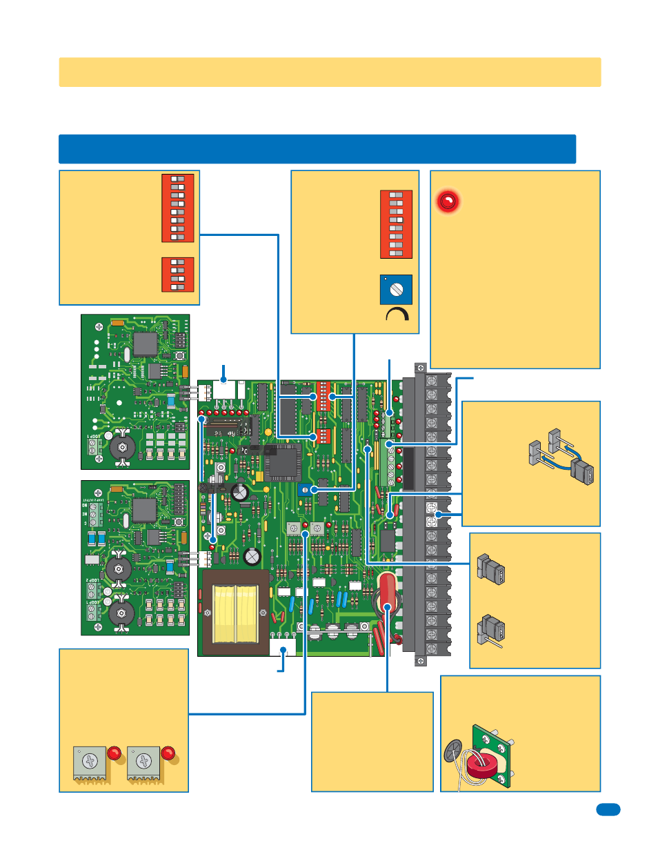
Page 19: Dry relay contact, Plug-in loop detectors, Secondary interface terminal plug, Primary current sensor, Secondary current sensor
6550-065-A-4-12
17
20
19
18
17
16
15
14
13
12
11
10
9
8
7
6
5
4
3
2
1
1
ON
SW 1
2
3
4
1
ON
SW 2
REVERSE
LOOP
P2
P8
EXIT
LOOP
SELF
TEST
NC
TIME
DELAY
NO
REV SENSE
PRIMARY
REV SENSE
SECONDARY
1
2
3
4
5
6
7
8
9
13
12
11
10
14
15
16
17
18
19
20
2
3
4
5
6
7
8
9410
Single
Channel
4405-010
SECTION 3 - ADJUSTMENTS
The switch settings and adjustments in this chapter should be made after your installation and wiring to the operator(s) is
complete. Whenever any of the programming switches on the circuit board are changed, power must be shut-off, and then
turned back on for the new setting to take effect.
3.1 4405 Circuit Board Descriptions and Adjustments
Auto-close timer
(when turned on)
SW 1, switch 4.
Time Delay:
Adjust from 1 second
(full counter-clockwise)
to approximately 23
seconds (full clockwise).
Self-test mode is for
bench checks ONLY!
The operator will
continually cycle the gate.
The jumper must be set
at normal mode for
normal operator function.
Set the DIP-switches on
the circuit board to the
desired setting. See
switch-settings on next
2 pages.
SW 1
SW 1
Self-Test
Mode
Normal
Mode
SW 2
Plug-In Loop Detectors
(Sold separately)
Limit
Sensors
Plug P2
6-Pin UL 325 Removable
Terminal
See page 23.
Secondary
Interface
Terminal Plug
1
23
EXIT Loop T
erminal
REVERSE/SHADOW
Loop T
erminals
SHADOW Output T
erminal
Self-Test
Auto-Close Timer
How LEDs Function
DIP-Switches
Adjust reversing sensitivity for
the open AND close direction of
the PRIMARY (single) and
SECONDARY (dual) operators,
See page 21.
Inherent
Reverse Sensors
Power LED
Loop LEDs
Input LEDs
See page 25.
Illuminated LEDs
Indicates that
low voltage power is being
applied to the circuit board.
Input LEDs
should be OFF and will
only illuminate when the input is
activated.
Limit LEDs
will only illuminate when
the respective limit sensor has been
activated.
Loop LEDs
will only illuminate when a
reverse, shadow or exit loop is
activated (Vehicle passing over a
loop).
1
ON
2
3
4
5
6
7
8
1
ON
2
3
4
1
ON
2
3
4
5
6
7
8
EXIT Loop Port
REVERSE Loop Port
4-Pin Terminal
Not used for 6550.
Primary Current Sensor
Uses a sensing coil with a given
number of wire turns through it
to monitor the current flow of the
primary operator motor.
Factory Set:
1/2 HP Motor - 2 Turns
1 HP Motor - 1 Turn
Secondary Current Sensor
Uses a sensing coil with a given number of
wire turns through it to monitor the current
flow of the secondary gate operator motor.
Factory Set:
1/2 HP Motor - 2 Turns
1 HP Motor - 1 Turn
See page 22.
Secondary
Primary
9409
Dual
Channel
N.C.
N.O.
Dry Relay Contact
Terminals 10-11
can be set for
Normally Open
(NO) or Normally
Closed (NC) operation by placing
the relay shorting bar on the N.O. or
N.C. pins respectively.
(Standard shadow loop function, NO)
Limit LEDs
See page 20