Unwind frequency – CONTREX CX-1102 User Manual
Page 13
Page 11
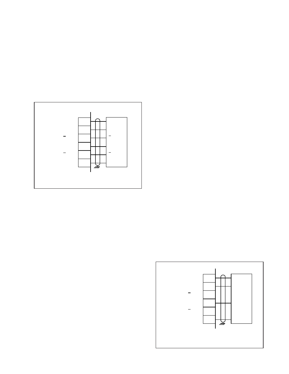
Unwind Frequency
(J5 pins 1, 2, 4, 5, 6)
The wiring for the Unwind Frequency is determined by the sensor. Figures 5 and 6 illustrate the wiring for
the various sensors. For signal level and performance specifications, refer to Appendices: Appendix A .
*
Total currant draw from the +5V_Aux (J5-Pin 1) should not
exceed 150 Milliamps.
Figure 5 Unwind Frequency
Quadrature Differential Sensor (Bidirectional)
Figure 6 Unwind Frequency
Quadrature Single-Ended Sensor (Bidirectional)
+5V Pwr
A
A
B
B
Common
1
2
3
4
5
6
J5
*
+5V_Aux
A
A
B
B
Com
Total currant draw from the +5V_Aux (J5-Pin 1) should not
exceed 150 Milliamps.
+5V Pwr
A
B
Common
1
2
3
4
5
6
J5
*
+5V_Aux
A
A
B
B
Com