Cx-1102 – CONTREX CX-1102 User Manual
Page 10
Page 8
+5VDC
Dncr
LnSpd
Com
1
2
3
4
JA
SigU
ComU
1
2
J3
SigW
ComW
1
2
J8
TD/RD +
TD/RD -
Com
1
2
3
J1
+V_DO
UwdEn
WdEn
UErr
WErr
WRlFl
Dncr
WbBrk
Spare
Com
1
2
3
4
5
6
7
8
9
10
J2
L1
L2/NEUT
GND/PE
1
2
3
J4
* +5VDC
A
A
B
B
Com
A
A
B
B
Com
RI_1
RI_2
1
2
3
4
5
6
7
8
9
10
11
12
13
J5
F-Stp
UnLd
Com
H-Stp
Load
Run
Spare
Com
KeyLk
Setup
1
2
3
4
5
6
7
8
9
10
J6
UJogF
UJogR
Com
WJogF
WJogR
UuWrp
WuWrp
Com
LSRvs
WbRst
1
2
3
4
5
6
7
8
9
10
J7
-
-
-
-
+5V PWR
A
A
B
B
Common
A
A
B
B
Common
+5V PWR
-
-
-
-
Unwind
Quadrature
Sensor
Wind
Quadrature
Sensor
NC
NC
F-Stop
UnLoad
H-Stop
Load
Run
Spare
Keypad Lockout
Setup
Unwind Jog Forward
Unwind Jog Reverse
Wind Jog Forward
Wind Jog Reverse
Unwind Under Wrap
Wind Under Wrap
Line Speed Reverse
Web Reset
RS485
Serial Comm
Digital Outputs
Control
Output
To Wnd Drv
AC POWER
INPUT
Encode Inputs
Reserved
Digital Inputs
UnWind
Wind
Control
Output
To UWnd Drv
Analog Card
R
R
R
R
R
R
R
R
Unwind Enable
Wind Enable
Unwind Error
Wind Error
Wind Roll Full
Dancer
Web Break
Spare
230 VAC
L1
L2
GND/PE
115 VAC
L1
NEUT
GND/PE
FUSES
1 A
250 V
RS485
Serial
Communications
Interface
EXTERNAL
DC
POWER
SUPPLY
(50V MAX)
+
-
Wind Motor Drive
Unwind Motor Drive
TD/RD +
TD/RD -
Com
Signal Input
Drive Common
Signal Input
Drive Common
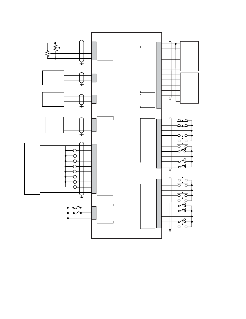
CX-1102
*
Power for frequency input sensors may be supplied by J5, pin 1.
Total current should not exceed 150 mA .
Dancer
Line Speed
Figure 3 CX–1102 General Wiring