B.4 modbus register information, Fieldbus communications – Hach-Lange AMTAX indoor sc User Manual
Page 112
112
Fieldbus Communications
Important Note: Do not try to change the listed register addresses, otherwise the
instrument may malfunction or become inoperable.
The Fieldbus register contains FFFFh (65536dec) when the feature is disabled.
A measurement series is initiated with entering "1" to register 40111 (Enter "2" for
2-channel instruments to start measurements on channel 2). The register will return to "0"
after the measurement series is done. The measurement results can be found at 40001
(channel 1) and 40165 (channel 2).
A value will appear every AVERAGE and at the end of a series if remind measurement(s)
exist. Example: NUMBER OF MEAS is set to 5 and AVERAGE to 2. The result are 3
values, the first is the average of measurement 1 and 2, the second is the average of
value 3 and 4, the last value is the reminding value of the 5th measurement
Note: Internal processes like calibration and cleaning will be interrupted from a measurement
series.The interrupted process will start after the end of the measurement series. To use the START
BY BUS feature, the sample has to be available for calibration, cleaning and rinsing purposes. An
ongoing measurement series will not be interrupted by internal processes.
B.3 External trigger contact, Control by external signal
If the controller board is equipped with an external input terminal (optional board version),
measurements can be issued by applying an external DC voltage of 15V to 30V to the
terminal for longer than 3 seconds. When the field bus control is activated, the input will
issue a forced measurement as described within Fieldbus control.
When the START BY BUS feature is activated, the external input will issue a
measurement series as described within the START BY BUS section.
Note: Only measurements on channel 1 can be started with the external contact on 2 channel
instruments.
B.4 Modbus register information
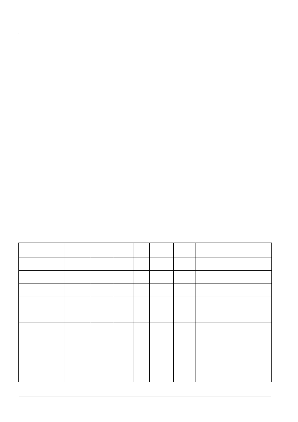
Table 13 Sensor Modbus registers
Tag name
Register #
Data
type
Length
R/W
Discrete
range
Min/Max
range
Description
MEASURE VALUE 1
40001
Float
2
R
—
—
Actual measurement value from
channel one
LOCATION1
40005
String
8
R/W
—
—
Name of LOCATION 1 (see menu
system)
MEAS.UNITS 1
40013
Unsigned
Integer
1
R/W
0/2
—
Measurement units for channel 1;
0=mg/L, 2=ppm
CUVETTE TEMP.
40014
Float
2
R
-50/
99.99
Actual cuvette temperature in °C
CALIB.INTERVAL
40016
Unsigned
Integer
1
R/W
0/1/2/3/4
Calibration interval; 0=OFF,
1=12h,2=24h, 3=36h, 4=48h
CALIB.START
40017
Unsigned
Integer
1
R/W
0/1/2/3/4/
5/6/7/8/9/
10/11/12/
13/14/15/
16/17/18/
19/20/21/
22/23
—
Acceleration time for calibration
(24 hour format) 0=0 o’clock to
23=23 o’clock
ENCLOSURE
TEMP
40020
Float
2
R
—
-50/
99.9
Temperature inside the analyzer