Cashco C-CS User Manual
Page 4
4
IOM-C-CS
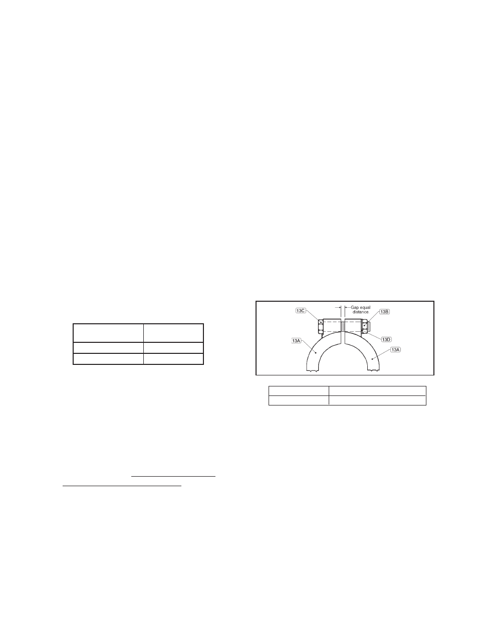
Figure 1: Clamp Arrangement.
together by hand. NOTE: Top of dowel
pin (25.8) should be fl ush with top surface
of adjusting screw cap (25.7).
22. Install new bearing (26) on top of upper
guide assembly (25).
23. Align slot guides inside spring chamber
(2) with spring button (4) tabs (ears) and
position on to body (1). Align with match
marks of step 6. previous.
24. Place handle (6) over end of guide post
(27) coming to rest on adjusting screw cap
(25.7). Insert hitch pin (21) into hole through
end of guide post (27). Apply Loctite 242
or equalivent to threads of set screw (30)
install into top of guide post (27) and tighten
securely.
25. Reposition clamps (13A) around body (1)
and spring chamber (2) fl anges. Insert clamp
bolts (13C), washers (13D) and tighten
clamp nuts (13B) in alternating pattern.
NOTE: Gap be tween clamp (13A) halves
should be equal in size. Gap and torque
re quire ments are as follows:
26. Reapply compression to the range spring
(7) by rotating handle (6) CW as per the
num ber of revolutions re cord ed in VI.B.2.
27. Return to Section II for Installation and
Sec tion IV for Start-up.
13. Clean gasket (15) and O-ring (16) retaining
surfaces of body (1) and spring chamber (2).
14. Clean all parts in accordance with Own er’s
cleaning procedures. Reposition plug (14)
back into vise with body (1). Ensure that the
plug (14) is in contact with the seating area of
the body (1) and the face of the inlet fl ange of
the body (1) is resting on the vise.
15. Place new diaphragm gasket (15) on body (1)
fl ange.
16. Install O-ring (16). NOTE: For Opt.-11 re po si-
tion push er plate (20) on threaded end of plug
(14) and install O-ring (18) and seal (19). Refer
to Figure 4.
17. Place diaphragm (17) over threaded end of
plug (14). NOTE: The word ‘TOP’ is etched on
one side of the diaphragm and should be vis-
ible when looking down on the diaphragm.
18. Place a small amount of medium strength
threadlocker equal to "Blue 242 Loctite" on
threaded end of plug (14). Reassemble pres-
sure plate assembly (27,28 and 29) to plug
(14). Refer to NOTE: in Step 10. Grasp the
parts and rotate pres sure plate assembly
(27,28,29) CW until wrench tight (met al-to-
metal con tact); Torque values not to ex ceed
the following:
19. Center/align the above pressure plate/
diaphragm assembly on the di a phragm (17)
fl ange sur face in the body (1).
20. Position spring (7) on to hub of pressure plate
(28). Place adjusting screw (25.6) - with spring
button (4) - over end of guide post (27) and
into spring (7) cav i ty. NOTE: Apply a small
amount of Emhart Bostik White Food Grade
“Never-Seez” or equiv a lent to threads of ad-
just ing screw (25.6) Do Not rotate adjusting
screw (25.6) or spring button (4).
21. Install new guide seals (25.9) in adjusting
screw cap (25.7). NOTE: There are two sizes
of u-cup seals - install the seal with the big-
ger diameter spring fi rst, open face into the
cap recess. Install the second u-cap seal,
open face exposed to face of adjusting screw
(25.6). Slide adjusting screw cap (25.7) over
end of guide post (27). Align dowel pin (25.8)
with hole in adjusting screw (25.6) and press
Body Size
in (DN)
Torque
in-lbs (N-m)
3/4"-1 1/2" (20-40)
100 (11)
2" - 3" (50-80)
270 (31)
Gap Torque
Equal Distance 225-250 in-lbs (25-28 N-m)