Cashco 1000 LP User Manual
Page 6
IOM-1000LP-Basic
6
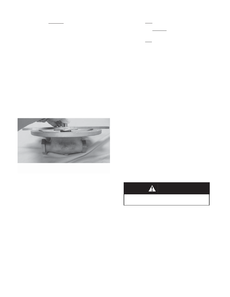
Checking diaphragm setting.
Barg) min i mum inlet pres sure to leak test.
Actual service con ditions should be used if
in ex cess of the minimum con di tions.
C. Special Instructions for Diaphragm
Removal.
1. If Option-3, Handwheel, is uti lized, the
ad just ing screw (6) and locknut (7) are
re placed by a handwheel (6.3)/adjusting
screw (6) assembly and locking le ver (7).
2. Use only gaskets of the same material as
original equipment. Cashco's Option-45,
non-as bes tos con struc tion, uti liz es spe cial
gas kets.
D. Diaphragm Setting Adjustment:
1. In the previous “Sub-Section B. Diaph ragm
Replace ment”, care was taken to prevent
re mov al of the stud collar (16) and stud nut
(10). Location of the stud nut (10) is a critical
ad just ment for a Model 1000 regulator.
2. Not removing the stud nut (10) will provide
per for mance equal to original factory per for-
over 0.020" (0.50 mm).
b. Diaphragm setting acceptable. Bar
lifts be tween 0.010"-0.020" (0.25-0.50
mm).
c. Diaphragm setting too low. Bar lifted
less than 0.010" (0.25 mm), or failed to
be lifted.
4. The castle style stud nut (10) has six lo ca -
tions per revolution to align the stud nut (10)
slots with the drilled hole thru the pusher
plate and stud (13). Each stud nut (10) slot
represents a movement up/down of 0.010"
(0.25 mm). NOTE: The ideal diaphragm
set ting is 0.015" (0.38 mm) high, and bet-
ter per for mance is usu al ly obtained when
the di a phragm is slight ly higher rather than
low er. As the measuring of thou sandths of
an inch is dif fi cult with such a procedure, it
is rec om mended that the “null” position be
found where the di a phragm (20) is fl ush
with the body (1) fl ange (bar ap prox i mate ly
at 0.000" (0.00 mm)). Remove the push er
plate and stud (13), rotate the stud nut (10)
one or two slots CCW to bring the setting to
0.010"-0.020" (0.25-0.50 mm) high.
5. Place cotter pin (15) thru the slot/hole, bend
over ends.
6. Continue re-assembly per Sub-Section B.
Di a phragm Replacement, Step 14.
E. Trim Removal and Replacement
1. Install body (1) horizontally in a vise with the
spring chamber (2) directed upwards, and
the body (1) held at the outlet end.
2. Loosen and remove the cylinder (21) by
turning CCW. NOTE: The piston (24) and
piston collar (23) should come out with the
cylinder (21) re mov al.
3. If an Option-17 piston spring (30) is utilized,
it also should be removed and re placed at
trim replacement.
4. Inspect inside surface of cylinder (21) at four
points:
a. Valve seat (21.2). Check for ero sion/
wear on seat ing surfaces. If wear is
ex ces sive, con sider uti liz ing Op tion
1000-15, stel lited seat sur faces.
b. Seat (21.2). Check for wire drawing
be tween cyl in der (21.1) and valve seat
(21.2) where pressed in. If wear exists
here, an Option-14, integral seat, should
be uti lized as a re place ment.
CAUTION F
m ance when a diaphragm(s) (20) is re placed
with a like diaphragm(s) (20). How ever, if
the stud nut (10) is removed, or a switch is
made from metal to composition diaphragm
(20), or vice versa, the dia phragm setting
should be checked.
3. Follow procedure “Sub-Section B. Dia-
phragm Re place ment” to the point of re mov-
ing diaphragm(s) (20), Step 14. Remove
di a phragm gasket (19) and pusher plate
stud gas ket (12). Obtain a fl at 12" x 1-1/2"
x 1/4" (300 mm x 40 mm x 6 mm) plate bar
with a 3/4" (20 mm) hole drilled in the cen-
ter. Hook the pusher plate and stud (13)
into the rocker arm (14) prongs prop er ly.
Pull fi rmly up on the pusher plate and stud
(13) to ensure that all slack is re moved from
the mech a nism and that the piston (24) is
seat ed fi rmly. Relax the pulling and place
the fl at bar over the pusher plate and stud
(13) with the stud (13) passing thru the hole
of the bar. Again, pull fi rmly up to remove
mech a nism slack. One of three positions
will be reached:
a. Diaphragm setting too high. Pusher
plate and stud (13) will lift the fl at bar
Do not allow the pis ton (24) to fall from within the
cylinder (21); tip cylinder with hex end down.