Cashco 1000 LP User Manual
Page 5
IOM-1000LP-Basic
5
Body Size
Metal Diaphragm
Comp. Diaphragm
1/2"
35-40 ft. lbs.
25-30 ft. lbs.
3/4"-1"
45-50 ft. lbs.
35-40 ft. lbs.
DN 15
47-54 N-m.
34-41 N-m.
DN20-DN25
61-68 N-m
47-54 N-m
17. Remove cotter pin (15) se cur ing stud nut
(10) to lower end of pusher plate and stud
(13), and replace with a new pin (15). (Do
not allow the stud nut (10) to rotate when
the cotter pin (15) is re moved.)
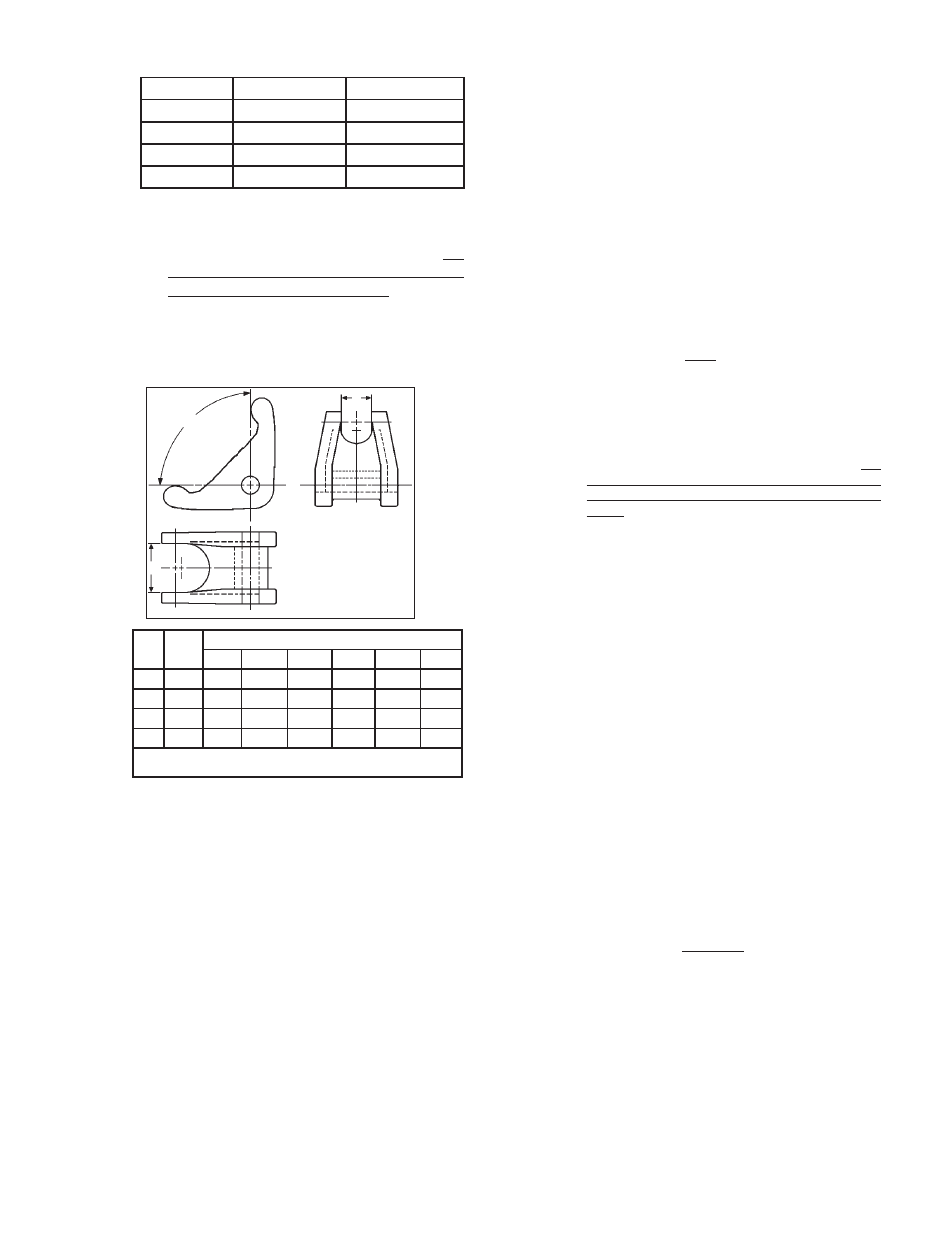
18. Remove rocker arm shaft (17) and rocker
arm (14). Measure inside of rocker arm (14)
“prongs” as indicated below:
pres sion. It may also adversely change the
di a phragm setting, which will affect the unit's
per for mance, i.e. Option-45, non-as bes tos
construction utilizes special gaskets.
21. Using small gauge wire approximately 18"
(500 mm) long. Form a hook and place the
hook over one prong of the rocker arm (14).
Rotate the rocker arm (14) up until slack is
removed in the mechanism. Hold the wire
above the body (1) fl ange on the outlet side
of the valve.
22. Take the diaphragm sub-assembly (Step 16)
and lower it down into the body (1) cavity
off-center approximately 3/4"-1" (20-25 mm)
towards the inlet side of the valve. When
fully low ered, slide the di a phragm sub-as-
sem bly horizontally to wards the valve's
out let. The wire of Step 21 should hold the
rocker arm (14) up to allow the pusher plate
(5) and stud (13) (with stud nut (10) and stud
collar (16)), to slide underneath the rocker
arm (14) prongs. The rocker arm (14) prongs
must rest di rect ly on the stud collar (16). (Do
not allow the rocker arm (14) prongs to rest
between the stud nut (10) and the stud collar
(16).) Pull fi rmly to remove wire.
23. Align diaphragm (20) bolt holes with body
(1) fl ange bolt holes. Set range spring (27)
onto pressure plate (3), place spring but-
ton (4) on top of range spring (27). Place
multi-pur pose, high temperature grease into
de pres sion of spring button (4).
24. Aligning the matchmarks, place spring
cham ber (2) over the above stacked parts.
Install all bolts (8), nuts (9) and name plate
(28). Tight en bolt ing (8 and 9) in a cross
pattern that allows the spring cham ber (2)
to be pulled down even ly. Rec om mend ed
torque values* are as follows: All sizes
and di a phragms: 35 Ft-lbs (47 N-m)
25. Reinstall
ad
just ing screw (6) with lock nut
(7). Install closing cap (31) if pro vid ed.
26. Spray liquid leak detector to test for leak age
around bolt ing (8 and 9), body (1) and spring
cham ber (2) fl anges, and cyl in der (21) to
body (1) joint. Ensure that an outlet pressure
is main tained during this leak test of at least
mid-range spring level; i.e. 15-30 psig (1.0-
2.1 Barg) range spring, 23 psig (1.6 Barg)
test pres sure min i mum. Use 100 psig (7.0
* Minimum recommended torque values regardless of
gas ket ma te ri als. Some gasket materials may require
higher bolt torques to obtain adequate seal.
Gasket
ma
te ri al may take a “set” with time; a re check
of torque values should be made if the unit has been
stored on the shelf for over 30 days.
NOTE:
Never replace bolting (8 and 9) with
just any bolting if lost. Bolt heads and nuts are
marked with specifi cation iden ti fi ca tion num bers.
Use only proper grades as re placements.
"
A
"
90°
"
B
"
DIM
MAT'L
Valve Size
1/2"
DN15
3/4"
DN20
1"
DN25
A
BRZ
7/8"
22 mm
1-5/32"
29 mm
1-7/16"
37 mm
B
BRZ
5/8"
16 mm
25/32"
20 mm
3/4"
20 mm
A
SST
13/16"
21 mm
1-1/16"
27 mm
1-7/16"
37 mm
B
SST
9/16"
14 mm
23/32"
18 mm
3/4"
20 mm
If any of the above dimensions are exceeded by 1/8" (3 mm), replace rocker
arm (14)
19. Check rocker arm shaft (17) for wear and
straightness. Replace if damaged. Rein-
stall in body (1) thru rocker arm (14). Apply
thread sealant to the rocker arm shaft (17)
threads prior to tightening. Make sure that
the rocker arm shaft (17) enters the sup-
port slot op po site the threaded open ing and
does not align crooked or re strained from
full thread en gage ment with the body (1).
Make sure the rocker arm (14) prongs that
strad dle the piston (24) hold the piston collar
(23) against the piston (24). Do not allow the
rocker arm (14) prongs to push directly on
the piston (24).
20. Clean the body (1) diaphragm fl ange. Install
a new diaphragm gasket (19). Composition
(soft) diaphragms require no diaphragm
gas ket. NOTE:
Use only gaskets man u fac-
tured by Cashco, Inc. that are of the same
ma te ri al as those originally supplied. Sub-
sti tu tion may cause improper gasket com-