Warning – Cashco DA4 User Manual
Page 5
IOM-DA4
5
12. Remove the ITA by pulling up on the valve
plug (20). Set ITA aside.
13. Remove the lower piston spring (22), as ap-
pli ca ble, from within the body (23).
14. Remove o-ring cage seal (15).
15. If supplied, remove internal sensing drilled
plug (32) using 5/32" (4 mm) Allen wrench.
16. Remove body (23) from vise. Clean all
re us able metal parts according to owner's
pro ce dures.
C. Disassembly of the ITA:
1. Units with Composition Diaphragm(s) (See
Figure 2):
a. Pull the valve plug (20) down wards and
out of the piston-guide bear ing (13) and
out of the cage's (19) bottom, while hold-
ing the cage (19).
b. Remove the piston-guide bearing (13)
from the upper end of the cage (19).
B. Main Valve Disassembly:
1. Shut down system in accordance Section VI.
2. Disconnect the external sensing line, if in-
stalled.
3. Though it is possible to disassemble the
valve unit while installed in a pipeline, it is
rec om mend ed that maintenance be done in
a shop when possible. The descriptions here-
after will assume shop disassembly. Remove
valve from pipeline.
4. Place the valve unit in a vise with the cover
dome (25) upwards.
5. Loosen the diaphragm fl ange bolts (11) and
nuts (12) uniformly.
6. Place matchmarks on body (23) and cover
dome (25) fl anges. Remove cover dome (25).
7. For composition diaphragm construction, hold
the milled “fl ats” on top of the valve plug (20)
stationary. Loosen and remove the di a phragm
lock nut (7). NOTE: Metal di a phragm con struc-
tions do NOT have a di a phragm lock nut (7).
8. Remove upper diaphragm pressure plate (8).
9. Remove diaphragm(s) (9, 9.1, 9.2, 9.9) and
o-ring upper stem seal (14.1). Examine
diaphragm(s) to determine whether failed;
determine if op er at ing conditions are ex-
ceed ing pressure, pressure drop or tem-
perature limits.
10. For composition diaphragm construction,
re move lower diaphragm pusher plate (10).
11. Evenly loosen the three cage cap screws (18)
in single revolution increments. Regulator
may con tain a lower piston spring (22); the
ITA should rise as the cage cap screws (18)
are evenly backed out. A down wards hold-
ing force should be ap plied to the top of the
piston-guide bearing (13) to pre vent the ITA
from pop ping up as the last threads of the
cage cap screws (18) are backed out.
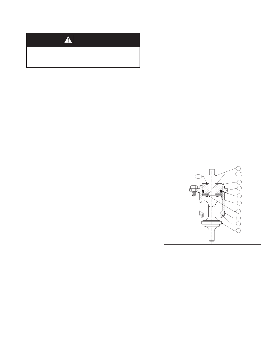
Figure 2: Assembled ITA,
Composition Di a phragm Construction
c. Remove o-ring middle stem seal (14.2)
from piston-guide bearing (13).
d. Examine the com po nents (27.1, 27.2,
27.3, 27.4, 27.5, 27.6) of the dy nam ic
side seal (27) mechanism to de ter mine if
sig nifi cant leakage was oc cur ring. If the
dy nam ic side seal (27) shows signs of
sig nifi cant leakage, de ter mine if op er at-
ing con di tions are ex ceed ing pres sure,
pres sure drop, or tem per a ture limits.
Remove dynamic side seal (27) com po-
nents. Special care should be taken when
using “tools” to remove the components
20
21
19
17
16
15
27
13
14.3
20
14.2
WARNING
SYSTEM UNDER PRESSURE. Prior to per form ing any
maintenance, isolate the reg u la tor from the system and
relieve all pressure. Failure to do so could result in per-
sonal injury.