Cashco 9540R P/P User Manual
Page 6
IOM-9540R
6
19. Install adapter block (AB) with four O-rings
(OR) to main positioner unit, with the connec-
tions oriented to the rear.
20. Install tubing fittings with acceptable thread
sealant and tubing from the unit’s 1/4” NPT
(female) “OUTPUT 1” port of the adapter
block (AB) up to the connection port of the
actuator casing. NOTE
- Thread Sealants: If
TFE tape is used, make sure that small pieces
of tape will not be “pinched off” and enter the
pneumatic internals. (Liquid thread sealants
are not recommended.)
21. Place temporary fittings and tubing so that the
positioner is able to be supplied with a 20-35
psig air supply to the “SUPPLY AIR” port of
the adapter block (AB). Supply pressure de-
pends upon actuator bench setting; see Table
1. Using manual loader, connect a 3-15 psig
air source to the INPUT” (3-15 psig) “W” port
of the adapter block (AB).
(17) . If this occurs, the positioner unit must be
removed from the rotary baseplate (26). Using a
screwdriver, hand tighten the main shaft (17) by
turning CW (as viewed from main shaft (17) end)
as tightly as able while holding the stroke factor
lever (19) firmly against the travel stop pin (20).
23. Place decal (DC) onto indicator cover (22)
backside as indicated in Figure 5. Trim the decal
to remove the “120
°
” indication. Align the “0
°
”
position to the notch of the indicator cover (22);
the “0
°
”, “30
°
”, “60
°
” and “90
°
” tick-marks should
touch the outside arc of the clear portion of
indicator cover (22).
24. Check the valve’s actual position of the plug.
Place plastic red pointer (34) just barely onto
post-end screw (23). Calibrate pointer (34) to
indicator cover (22) by repositioning pointer (34)
as required. When calibration is satisfactory, press
pointer (34) firmly down over post-end screw (23).
25. Fasten clear indicator cover (22) into place using
two cap screws (A3).
26. Leave temporary air sources as installed for final
calibration, Section V, but turn off the air supply so
that no pressures are induced to the internals.
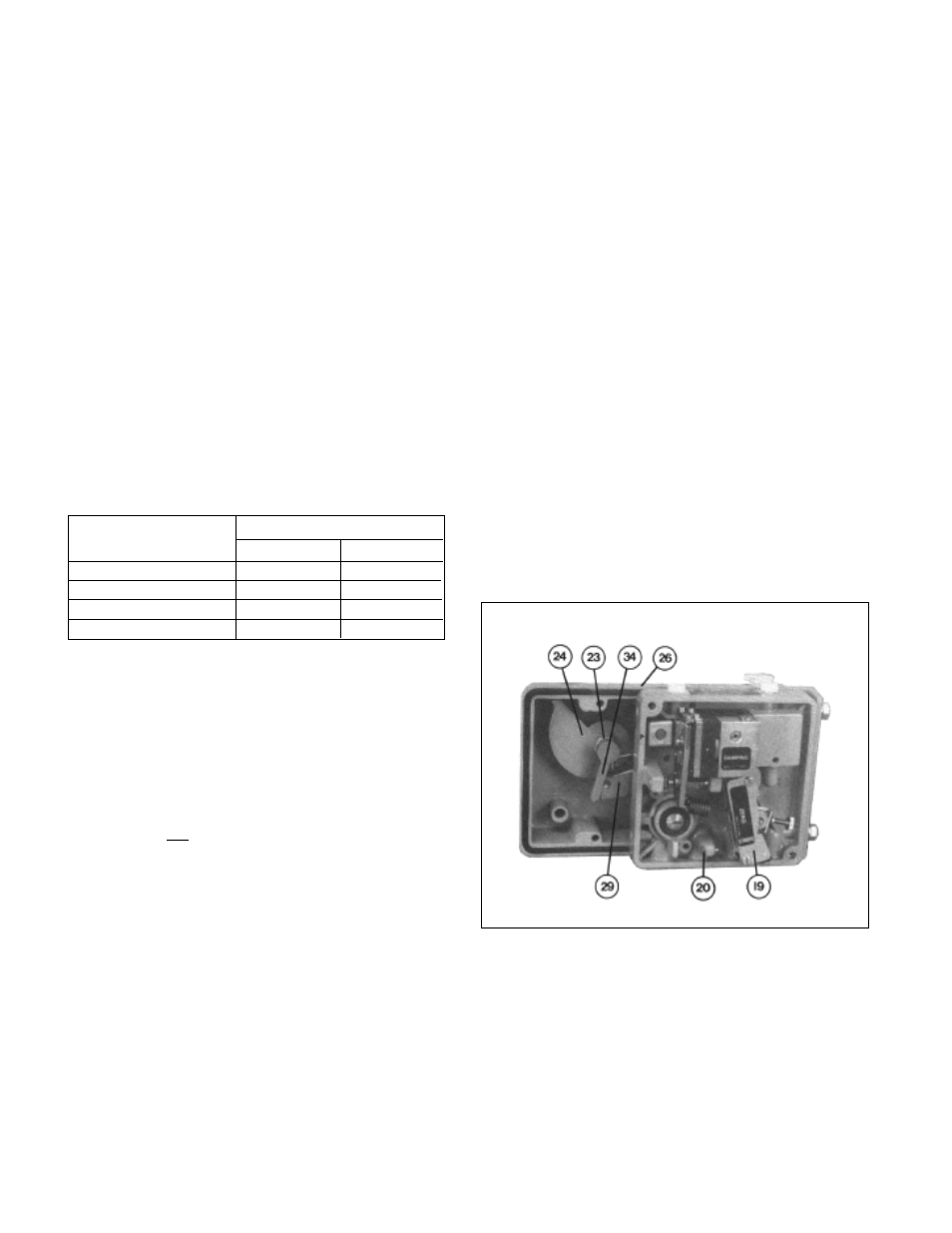
Figure 6
22. Slowly vary the pneumatic signal “SIG” input
and observe that the valve begins to stroke
from its failure (“LOAD” = 0 psig) position.
Observe the cam (24) to ensure that it appears
to be properly oriented. Fully stroke the valve
and observe for linkage interferences. Return
valve to closed position. Make a final
adjustment of the cam (24) using the spacer of
Step 6. Make sure that the cam follower (31)
does not enter the “valley” of the cam (24). (See
Figures 8-15.)
IMPORTANT NOTE:
If the feedback lever (13) is
turned forcibly against the travel stop pin (20), the
stroke factor lever (19) will be released from rigid
connection (unscrews) to the positioner main shaft
Table 1
Actuator Bench Setting Supply Pressure, psig (Barg)
psig
(Barg)
Recommend
Maximum
5-13
(.34-.90)
20
(1.4)
25
(1.7)
7.5-19.5
(.52-1.3)
27
(1.9)
30
(2.1)
10-26
(.69-1.8)
36
(2.5)
40
(2.8)
14-30
(.97-2.1)
44
(3.0)
45
(3.1)