Cashco 9540R P/P User Manual
Page 13
IOM-9540R
13
4.
The following procedure must be observed in
order to achieve a no-feedback adjustment of
the ZERO and STROKE setting.
a.
Press the stroke factor lever (19) against
the travel stop pin (20).
b.
Set the stroke factor thumbscrew (40) to
a high stroke factor (approximately 5/64”
before the upper stop).
c.
Turn the zero thumbscrew (39) until the
output pressure is mid-range of “SIG”
span and make a note of this value.
d.
Set the stroke factor thumbscrew (40)
to a low stroke factor (approximately
5/64” before the lower stop). The output
pressure may not vary by more than
±
0.003 psig as compared with the setting
described in c. above.
e.
In case of excessive deviations, the travel
stop pin (20) should be adjusted. When-
ever the travel stop pin (20) is adjusted,
the settings described in b. to d. should be
repeated until the deviation is less than
±
0.003 psig.
f.
Seal the travel stop pin (20) with sealing
paint.
5.
Return the changeover plate (15) to its origi-
nal positioner if it was “U”. Re-tighten the
feedback (13) lever onto the main shaft (17) of
the positioner (see Section III.D.8. & 9.).
6.
Go thru a complete calibration/adjustment
procedure as described in Section V.
B. Cleaning the Throttle Screw: (See Figure 18)
1.
Unscrew CCW the limiting screw (43). If you
can’t pull it out by hand, unscrew CCW the
throttle screw (42) and remove both by hand.
2.
Pull the throttle screw (42) out of the limiting
screw (43).
3.
Place the throttle screw (42) in solvent (e.g.
benzene) and blow through it carefully. It is
best to clean in an ultrasonic solvent bath.
4.
Turn the throttle screw (42) in again as far as
it goes CW.
5.
Turn the limiting screw (43) in as far as it goes
CW; then back it out CCW about half a revo-
lution.
6.
Secure the limiting screw (43) with sealing
paint.
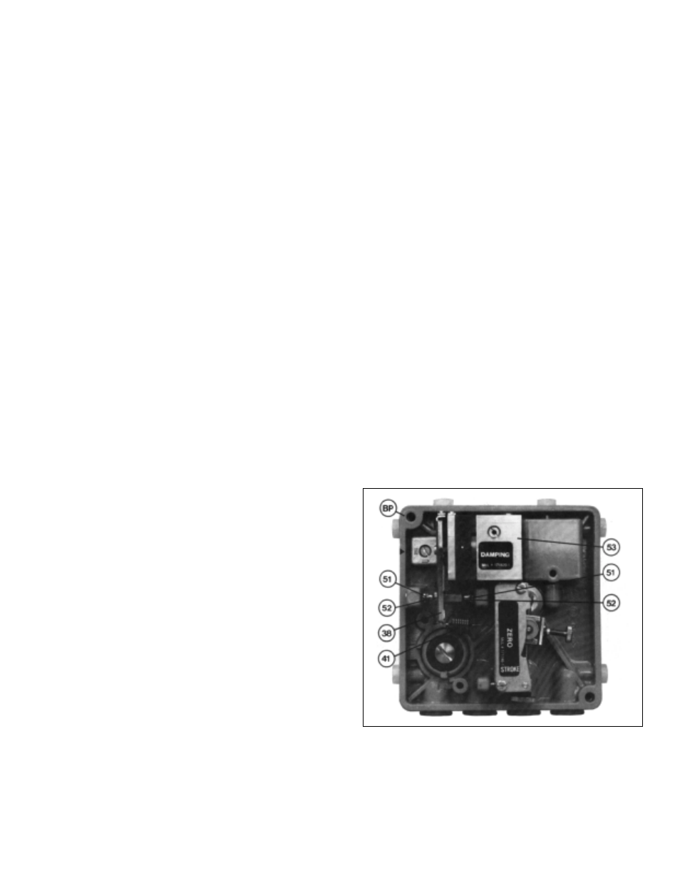
C. Replacing the Amplifier: (See Figure 21)
1.
Unhook the range spring (41) from the flapper
lever (38).
2.
Unscrew and remove the amplifier (53) sub-
assembly; the two amplifier mounting screws
are accessible from the rear of the positioner.
3.
Install a new amplifier (53). Do not forget the
O-rings between the amplifier and the base-
plate (BP) (air baffle). Before tightening, care-
fully align the mounting screws, position the
amplifier (53) in such a way that the flappers
(52) are concentrically aligned with the nozzles
(51).
4.
Hook the range spring (41) onto the flapper
lever (38).
5.
Perform a maintenance basic adjustment and
recalibrate per Section IV, V and VI.
Figure 21