Vi. maintenance – Cashco 9540R P/P User Manual
Page 12
IOM-9540R
12
2.
DAMPING is factory set, and normally re-
quires minimal/no adjustment. However, if
determined as required, DAMPING is adjust-
able from a minimum-to-maximum ratio of
1:2.5. In its normal factory set position, the
damping screw (44) is set approximately flush
with the amplifier housing (53); this position is
minimum DAMPING . As the damping screw
(44) is screwed CW - inwards, DAMPING
increases. DAMPING may be increased by
up to approximately three full revolutions of
the damping screw (44), which will represent
maximum DAMPING.
VI. MAINTENANCE
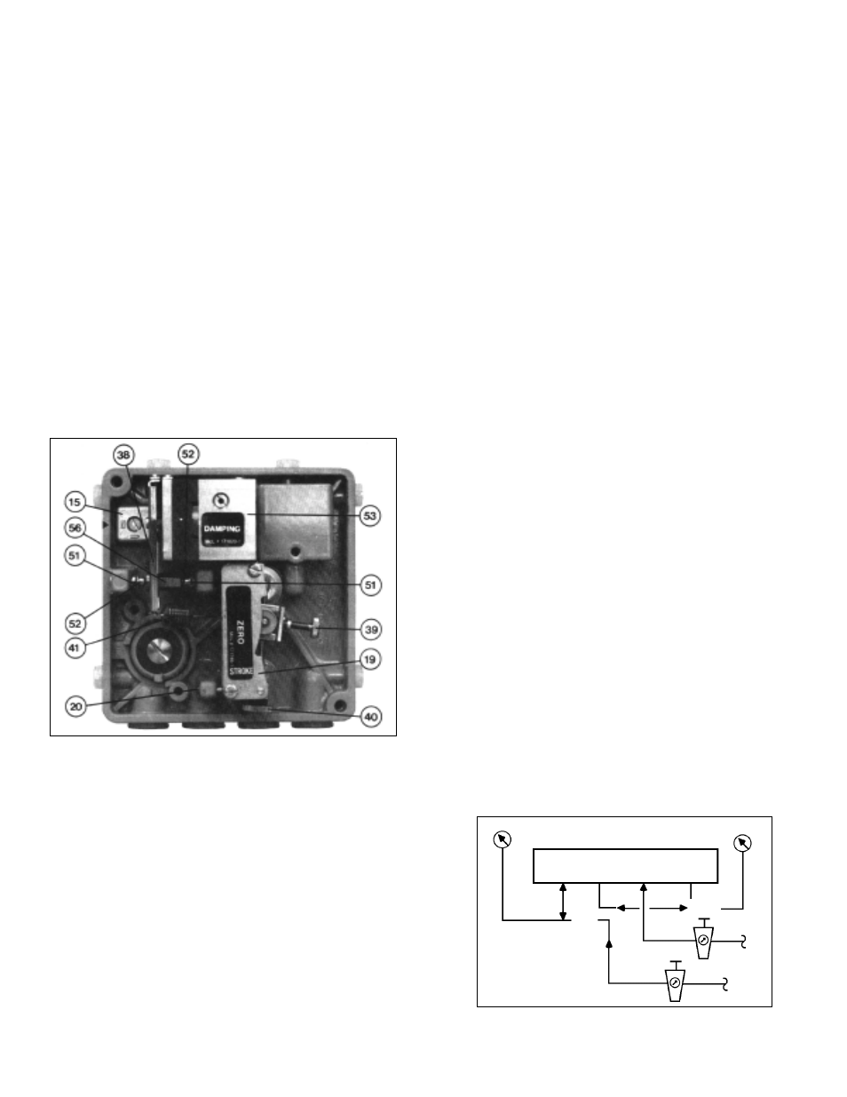
A. Adjustment of the Positioner: (See Figure 19)
1.
Component adjustment is only required when
the positioner has been disassembled or sub-
assemblies have been exchanged. All set-
tings performed in order to match the positioner
to the actuator are described in Sections IV.
and V.
2.
See Section IV.A. for a list of required tools.
3.
If adjustments are made with the positioner
mounted on the control valve, the feedback
lever (13) on the main shaft (17) of the
positioner must be loosened. (See Section
III.D.11.-12.).
a.
Set the changeover plate (15) to “N”.
b.
Turn the throttling screw (42) CW to its
stops (maximum GAIN).
c.
Unhook the range spring (41) from the
flapper lever (38).
d.
Check that the flappers (52) are aligned
concentrically with the nozzles (51). (If
necessary, loosen the AMPLIFIER mount-
ing screws on the rear of the positioner
and align the amplifier (53) sub-assembly
accordingly; this will require removal of
the main positioner unit from the rotary
baseplate (26). )
e.
Press the flapper lever (38) several times
alternately to the left and right, so that the
ball-and-socket mounted flappers (52) are
aligned parallel to the nozzles (51).
f.
Press the flapper lever (38) to the left. Set
the clearance between the nozzle (51)
and the flapper (52) to 0.6 mm (0.024 in.)
with the aid of a feeler gauge by turning
the hexagonal adjuster (56) with 6 mm
wrench. Secure the nut against further
turning using sealing paint.
g.
Connect the positioner as shown in the
test circuit in Figure 20. Provide an “IAS”
of 60-100 psig.
h.
Press the flapper lever (38) to the left. If
the output does not rise to the level of the
supply air pressure, either leaks are
present or the flapper (52) is not correctly
aligned (repeat e. above).
I.
Hook the range spring (41) onto the flap-
per lever (38), and provide a mid-range (9
psig for 3-15 psig signal range, 6 for 3-9,
12 for 9-15, etc.) input “SIG” to port “Input
W” (3-15 psig) using a manual loader.
Figure 20
SECTION VI
Figure 19
Test Gauge
Test Gauge
MANUAL
LOADER
AIRSET
IAS
IAS
SIG
3-15 psig
See Table 2
for pressure
required
Input
W
Output
1
Supply
Air
Output
2
LOAD