Cashco 9540R P/P User Manual
Page 11
IOM-9540R
11
k.
If procedures of Step 4. above have been
completed, skip Step 5. following, and go
to next paragraph V.B.
5.
Press the flapper lever (38) several times to
the left and right until the flappers are correctly
aligned.
a.
Induce the minimum value of the input
signal (“SIG”) using a manual loader.
(This corresponds to the start of the valve’s
stroke.)
b.
Turn the zero thumbscrew (39) either CW
or CCW until the actuator begins to cause
valve stem travel. Precisely adjust to the
point where travel just begins.
c.
Induce the maximum value of the input
“SIG”. (This corresponds to the end of the
valve’s stroke.)
d.
Turn the stroke factor thumbscrew (40)
first CCW until observing the shortening
of the valve’s stroke (less than 90
°
). Turn
the stroke factor thumbscrew (40) CW
until the valve travel (90
°
) is precisely at
its full stroke.
e.
Recheck the ZERO and STROKE set-
tings. They should repeatable. Under this
procedure for adjustment, the ZERO and
STROKE calibrations are mutually inde-
pendent (i.e. non-interacting, when the
feedback lever (13) and travel stop pin
(20) are properly installed and positioned).
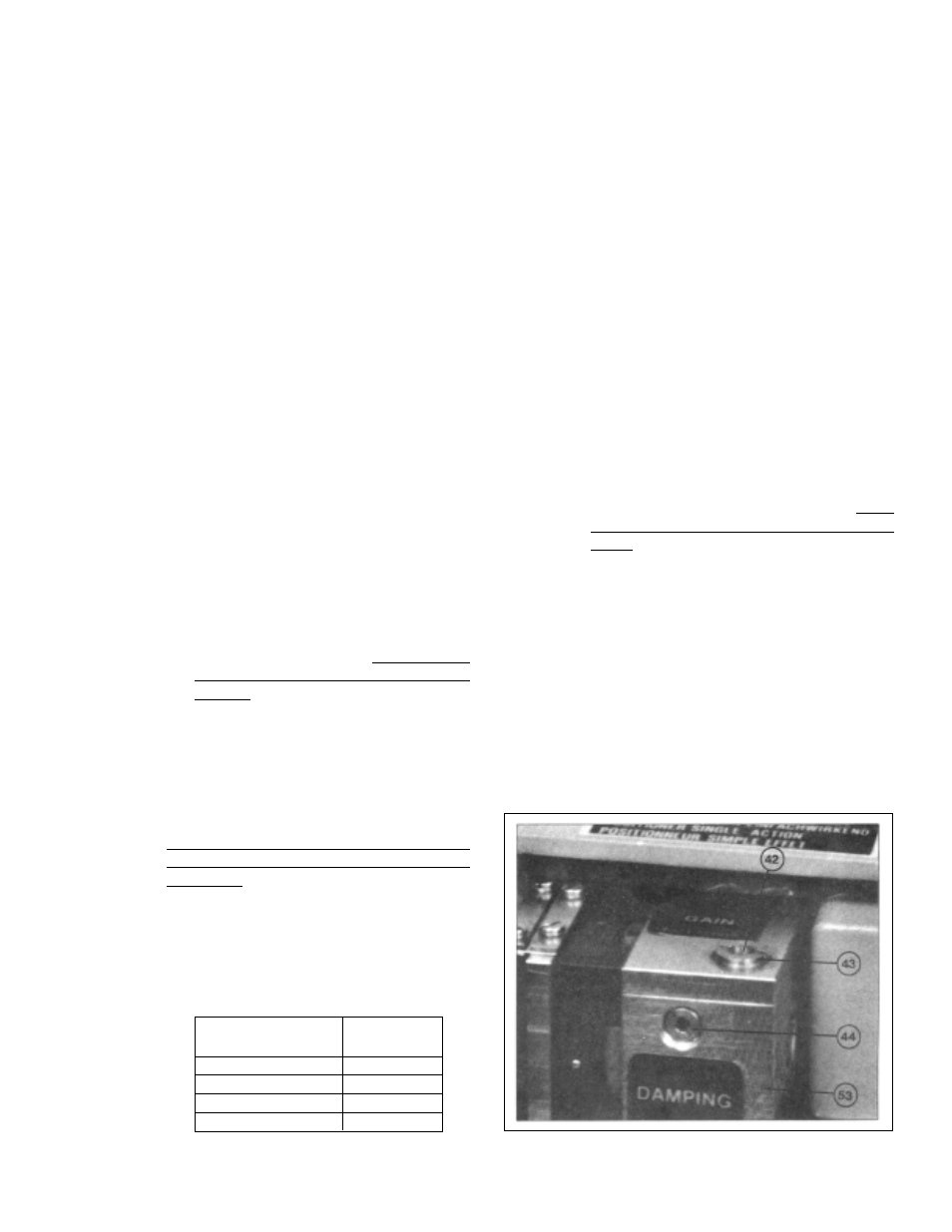
B. Setting GAIN: (See Figure 18)
1.
Increasing GAIN increases the sensitivity of
the positioner to change in the input “SIG”.
GAIN is normally factory set when mounted
by the factory, and should not require field
adjustment.
2.
The open loop gain varies with the supply
“IAS” pressure, and the values represent lin-
ear amplification. Table 4 is a guide to the gain
available for each range spring (41) utilized:
3.
A change in GAIN is normally indicated when
instability/sluggishness shows up at steady
state operating conditions. If the positioner
output “LOAD” seems to rapidly oscillate (psst-
psst-psst...), too much gain is present and
GAIN setting should be reduced until stability
is reached. If the positioner output “LOAD”
does not react to small changes in the “SIG”,
insufficient GAIN may be present; increase
GAIN until instability (psst-psst-psst...) is
present, then reduce as described previously.
This procedure allows the gain of the control
loop to match the dynamic requirements of
the control system.
4.
Determine whether GAIN should increase or
decrease based on above text. To increase
GAIN, rotate throttle screw (42) CW; to de-
crease GAIN, rotate throttle screw (42) CCW.
To prevent over-adjustment, the throttle screw
(42) is located within the limiting screw (43).
This allows the throttle screw (42) to only be
adjustable a total of approximately one revo-
lution from maximum to minimum. Thus, GAIN
should be adjusted slowly in very small incre-
ments.
5.
If GAIN is adjusted, ZERO resetting may be
required. Repeat Procedure V.A.
C. Setting DAMPING: (See Figure 18)
1.
Increase DAMPING introduces extra time con-
stant to the output “LOAD” of the positioner.
DAMPING should be increased/decreased
depending on the time observed for the
positioner to respond to a large change in
input “SIG” during a non-steady state operat-
ing condition.
Figure 18
TABLE 4
Supply Pressure
Adjustable
psig
(Barg)
Range
20
(1.4)
150:1
27
(1.9)
140:1
36
(2.5)
124:1
44
(3.0)
113:1