Cashco 9540R P/P User Manual
Page 5
IOM-9540R
5
four cap screws (79). The bracket should end
up with four holes to mount the positioner unit
and its baseplate (26) as shown in Figure 2.8.
7.
Attach the baseplate and mounting bracket
(76) assembly to housing cover (13) using
four cap screws (78). Align baseplate (26) to
be parallel with bottom of valve's arm housing
(4). See III.C. NOTE:
Engage the tongue-
and-groove joint between the positioner
baseplate rotary shaft (32) and the spacer
(17) with its protruding set screw (77).
8.
Determine characterization cam's (24) proper
orientation as indicated in Figures 8 thru 15;
cut a spacer from wood or heavy cardboard to
the dimension “X” indicated.
NOTE:
Whether air-to-open (ATO) or air-to-
close (ATC), Cashco's Ranger QCT, Premier
(unlined) or Premier EZO all rotate clockwise
(CW) to “close” valve, or counter clockwise
(CCW) to “open” valve, when viewed from
stem (7) end.
9.
Place a thin film of adhesive, glue or pipe
thread sealant on the “back” side of cam (24)
to secure toothed lock washer (28) to cam
(24). Use post end screw (23) to correctly
align centers of these three parts (24, 27 &
28); do not allow the post-end screw (23) to
adhere to these parts.
10. Using the spacer of Step 8., position cam (24)
with adhered parts (27 & 28) up to the end of
positioner rotary shaft (32). Carefully screw-in
post-end screw (23) while holding cam (24) in
its approximate position. Hand-tighten post-
end screw (23) until certain that the washers
(27 & 28) have remained in alignment. (If
washers (27 & 28) are misaligned, the cam
(24) will not be able to be secured.)
11. Using the spacer of Step 6. above, wrench-
tighten post-end screw (23) into a preliminary
position.
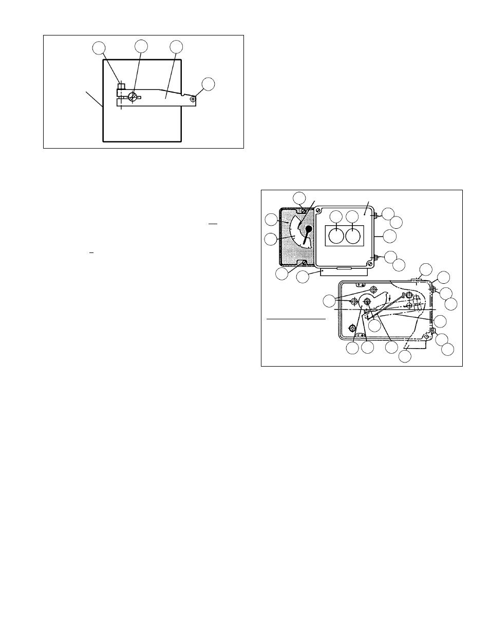
Figure 4 - Rear View
Main
Positioner
Unit
21
17
13
31
12. As shown in Figure 4, attach the feedback lever
(13) onto the positioner unit’s main shaft (17) by
hand-tightening socket cap screw (21). DO
NOT WRENCH TIGHTEN SCREW (21).
13. Remove the two plastic screws in the right side
of the main positioner unit where cap screws
(11) would be inserted. (See Figure 5.)
14. Begin to set the main positioner unit near its
final position on baseplate (26). Using needle
nose pliers grasp compensating spring (18)
and “hook” the end of the spring (18) under the
lower side of the feedback lever as indicated
in Figure 5.
Figure 5
A3
11
12
WC
11
12
G2
G1
22
DC
A3
AB
33
26
11
12
13
11
12
AB
18
17
31
24
A1
"Notch"
Main Positioner
Unit
15. Position the positioner unit onto baseplate
(26), ensuring that the feedback lever’s (13)
roller is placed into contact with characteriza-
tion cam (24) into the approximately proper
location. (See Figures 8 thru 15.)
16. Fasten the positioner unit to the baseplate
(26) inserting two cap screws (11) with lock
washers (12) thru the side of baseplate (26).
17. Remove the positioner cover (WC). Remove
plastic plug (33) from the upper edge of base-
plate (26), allowing access to the socket cap
screw (21).
18. Press the stroke factor lever (19) (See Figure
6) of the positioner’s internals against the
travel stop pin (20) and hold firmly in place.
Using the #5 Allen wrench provided, tighten
socket cap screw (21) to the main shaft (17)
while holding the stroke factor lever (19).
Replace plastic plug (33).
G2 = Air Supply "IAS"
G3 = Output "LOAD"
Illustrated Position:
Ait to Close
Fail Open