Ii. method of operation, Iii. mounting to spring diaphragm actuators – Cashco 9540R P/P User Manual
Page 2
IOM-9540R
2
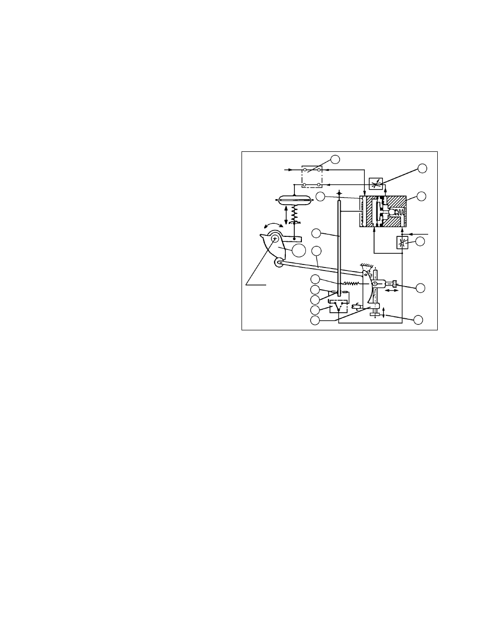
II. METHOD OF OPERATION
(See Figure 2
)
The positioner operates with the force balance
principle: the input signal “SIG” (3-15 psig) acts on the
input diaphragm (50). The stroke of the input
diaphragm is transferred to the flapper lever (38). The
resulting movement of the flapper varies the dynamic
pressure at the nozzle (51). This pressure acts on the
amplifier (53) and the change in output pressure
causes a movement of the valve’s rotary stem.
The rotary movement is back fed from the valve stem
(55), thru a characterization cam (24), to the feedback
lever (13) of the positioner, and transferred to the
stroke factor lever (19). The stroke factor lever (19) is
connected to the flapper lever (38) by means of a
range spring (41).
A force balance is created on the flapper lever (38)
when the force generated by the input diaphragm (50)
balances with the counter-force produced on the range
spring (41). This ensures that the valve stem position
is always characterized to the input signal.
Dynamic matching to the actuator (sensitivity, stabil-
ity) is factory set by means of the throttle screw (42)
and the damping throttles (44). The stroke range and
zero are set by means of the stroke factor thumbscrew
(40) and the zero thumbscrew (39). The changeover
plate (15) is used to set either an increasing or
decreasing output pressure for an increasing input
signal, i.e. direct or reverse acting.
The normal factor set position of the bypass switch (3)
is “EIN” (ON) (pointer at 6 o’clock), and the positioner
will be operational. If the positioner bypass switch (3)
is set to the “AUS” (OFF) position (pointer at 9 o’clock),
the input signal “SIG” is supplied direct to the actuator;
i.e. the positioner is only practical for control valves
where the positioner action is “Direct” and the actuator
bench range is approximately equal to the 3-15 psig
“SIG”. Use of bench ranges with upper limits greater
than 15 psig will cause the control valve to not be able
to fully stroke when bypassed.
III. MOUNTING TO SPRING DIAPHRAGM
ACTUATORS
A. The following text applies to the field mounting of
a positioner to a valve originally not supplied with
a shaft-end positioner. See Appendix A to remove
9000R.
B. Mounting Kit:
1.
A factory-supplied field mounting kit must
be obtained. Request “Model 9540R P/P
Field Installation Kit” (FIK) and indicate the
following:
a.
Unit’s serial number
b.
Product model; i.e. Ranger, Premier, or
Premier EZO
c.
Valve body size
d.
Actuator bench range
e.
Desired characteristic; i.e. =%, linear
f.
ATO-FC or ATC-FO action.
2.
An airset with gauge is required. Request
separately from positioner KIT.
3.
If a positioner indicating switch (by Bettis or
Proximity Controls) is shaft-end-mounted, the
use of the position switch(es) must be aban-
doned or replaced with probe-type proximity
switch(es) (“Go” Series 70) mounted on the
yoke. NOTE:
These units are available on
1” – 4” Rangers and 3” – 4” Premiers only.
C. Mounting Side:
When viewed from the valve stem end, with the
actuator casing defined as upwards (above stem),
the position indication portion should be to the
“left”, and the positioner section should be to the
“right’.
SECTION II
Figure 2: Single-Acting Positioner Functional Diagram
SECTION III
SIG
Travel
Valve
Stem
"LOAD"
"IAS"
N
U
Y
3
44
53
42
39
40
19
15
52
51
41
13
24
50
38