Cashco 9540R P/P User Manual
Page 10
IOM-9540R
10
V. CALIBRATION/ADJUSTMENTS
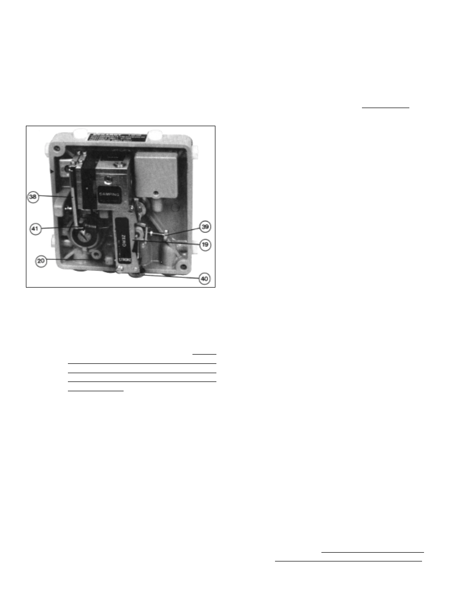
A. ZERO and STROKE Setting: (See Figure 17)
1.
After settings of Section IV have been com-
pleted, place separate manual loaders to
supply the positioner with air (“IAS”) and
develop a variable 3-15 psig signal (“SIG”) as
the input.
2.
Recheck character cam (24) position care-
fully. Loosen post-end screw (23) and
retighten as required to maintain dimension
“X” spacing per Figures 8 thru 15. Valve may
need to be stroked to ‘full open” or “full closed”
position to allow measurement of “X”. (NOTE:
Do not locate cam follower (31) in "valley” of
the equal % or linear cams (24) at either end
of stroke: follower (31) will always be slightly
out of the “valley”.) Stroke valve thru full travel
to ensure proper cam (24) orientation.
3.
If the positioner has an input “SIG” of 3-15,
3-9, or 3-7 (i.e. full stroke is a 15 psig, 9 psig,
or 7 psig “SIG” respectively for DIRECT
action; zero stroke at a 15 psig, 9 psig, or 7
psig “SIG” respectively for REVERSE action),
skip Step 4. following, and go to Step 5.
4.
If the positioner is split ranged for 9-15 or
11-15 psig “SIG” input (i.e. zero stroke is at a
9 psig or 11 psig “SIG” respectively for
DIRECT action; full stroke is at a 9 psig or 11
psig “SIG” respectively for REVERSE action),
then follow this procedure:
a.
Shut off supply air (“IAS”; i.e. 0 psig).
b.
Release all tension on range spring (41)
by turning zero thumbscrew (39) CCW.
c.
See Figures 4 and 5. Remove plastic plug
(33). Loosen screw (21) securing the feed-
back lever (13) on the backside of the unit to
the main shaft (17) using the #5 (5 mm) metric
Allen wrench provided. Manually move the
stroke factor lever (19) away from the tip of the
stop pin (20) a distance of approximately 1/4”
- 3/8” using some form of spacer; i.e. folded
cardboard, etc. Re-tighten feedback lever (13)
to main shaft (17). Remove the temporary
spacer. Replace plastic plug (33).
d.
Introduce an air supply (“IAS”) to the positioner
as required by Table 1.
e.
Press the flapper lever (38) several times to
the left and right until the flappers are correctly
aligned.
f.
Set the minimum input “SIG” with the manual
loader; i.e. 9 psig for 9-15 psig, 11 psig for 11-
15 psig.
g.
Turn zero thumbscrew (39) CW, increasing
tension of range spring (41), until the actuator
begins to move away from its zero (shelf)
position. (If adjustment does not cause valve
response, turn off air supply (“IAS”) and return
to 4.c. above; increase the temporary spacer
thickness in increments of 1/8” and repeat
steps until the valve does move.) Care should
be taken to ensure that the stroke factor lever
(19) does not over-travel from the starting
point to the point where the stroke factor lever
(19) will hit the housing cover (WC), before
reaching its end position - approximately 39
°
rotation.
h.
Induce the maximum input “SIG” with the
manual loader; i.e. 15 psig for 9-15 psig or 11-
15 psig.
I.
Turn the stroke factor thumbscrew (40) CW;
this shortens the valve stroke with respect to
the “SIG” change; i.e. less air pressure re-
quired to reach valve’s maximum stroke posi-
tion. Once valve stem moves with each CW
adjustment of the stroke factor thumbscrew
(40), reverse to CCW rotation of stroke factor
thumbscrew (40) and precisely adjust up to
the maximum stroke position of the control
valve.
j
Repeat Steps e. and h. a minimum of three
times, as under this adjustment of Steps b.
and c. above, the STROKE and ZERO adjust-
ments are mutually dependent; i.e. interacting.
Figure 17
SECTION V