Wiring the input power: caution – Fluid Components International ST98_ST98L Guide User Manual
Page 6
Mode ST98 Flowmeter
6
Doc. No. 06EN003310 Rev. -
FLUID COMPONENTS INTL
INSTALLATION, OPERATION AND TROUBLESHOOTING GUIDE
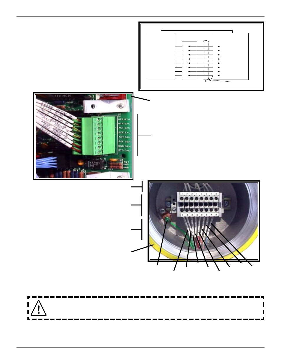
Wiring the Remote Instrument (Option):
Install a shielded, 8 wire cable between the remote
enclosure and the local enclosure as shown.
The Shield wire and the Heater Return wire must
be connected together and inserted into the connector.
The connector is plugged into the connector (TS2)
at the top of the board as shown. Use the schematic
representations of the mechanical assemblies as a wiring
guide.
RTD GND 1
GND SEN 2
REF SEN 3
ACT SEN 4
REF EXC 5
ACT EXC 6
HTR EXC 7
HTR RTN 8
BOARD ASSY.
P/N 017749
TS2
1
2
3
4
5
6
7
8
LOCAL
ENCLOSURE
TB1
SENSOR
ELEMENT
USE 8 CONDUCTOR SHIELDED CABLE ONLY
RTD GND 1
GND SEN 2
REF SEN 3
ACT SEN 4
REF EXC 5
ACT EXC 6
HTR EXC 7
HTR RTN 8
SHIELD
14 AWG GROUND SAFETY WIRE
TOP EDGE OF CIRCUIT BOARD
IN REMOTE ENCLOSURE
WIRING TO REMOTE
ENCLOSURE
FLOW ELEMENT WIRES
TERMINAL BLOCK
LOCAL
ENCLOSURE
CABLE FROM LOCAL
ENCLOSURE
(Shield and HTR RTN are
connected here)
NOTE: The Shield Is Not
Connected To Or In
The Local Enclosure.
Wiring the Input Power:
Caution:
FCI recommends placing an ON/OFF switch in line with the power source. When TS1 or TS4 is
connected to the power source, the instrument is ON.
AC or DC power (not both) can be used to operate this instrument. For best results route the output signal wiring through the
opposite port from the power input wiring. See the wiring table on the previous page to determine the size of wiring to be used
versus the length of the wire run to the power source.
RTD
ACT
REF
ACT
REF
HTR
HTR
GND
SAFETY