Step 4. wiring the instrument, Caution: alert – Fluid Components International ST98_ST98L Guide User Manual
Page 5
Doc. No. 06EN003310 Rev. -
5
Model ST98 Flowmeter
INSTALLATION, OPERATION AND TROUBLESHOOTING GUIDE
FLUID COMPONENTS INTL
A.
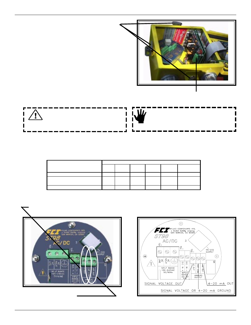
Loosen the hold down tabs on the
square (carbon steel) enclosure (3 places)
and open the lid. This gains access
to the instrument’s electronics.
B.
Route conduit to the enclosure. Wire the
customer termination board per the wiring
information on the next pages.
C.
When finished wiring, close the enclosure and
tighten the hold down tabs. See the Installation
Section in the ST98 Manual, Document
Number 06EN003291 for more details.
Step 4. Wiring the Instrument
The instrument contains electrostatic discharge
(ESD) sensitive devices. Use standard ESD
precautions when handling the flow transmitter.
Wiring the Instrument into the Customer Application:
This section describes proper wiring to the transmitter inputs, outputs and interconnection cabling for the optional remote
configuration. For best results route the output wiring through the opposite port from the power wiring. See the table below to
determine the size of wiring to be used versus the length of the wire.
Only qualified personnel are to wire or test
this instrument. The operator assumes all
responsibilities for safe practices while wiring
or troubleshooting.
M a x im u m D i s t a n c e f o r A W G
C o n n e c t io n
1 0 f t . 5 0 f t .
1 0 0 f t. 2 5 0 f t. 5 0 0 f t .
1 0 0 0 f t.
( 3 M )
( 1 5 M )
( 7 6 M )
( 7 6 M )
( 1 5 2 M ) ( 3 1 0 M )
I n p u t P o w e r
2 4
2 4
2 4
2 0
1 8
1 6
S e n s in g E le m e n t C a b le
2 4
2 4
2 4
2 4
1 6
1 6
( R e m o te In s tr u m e n t )
A n a lo g O u tp u t
2 4
2 4
2 4
2 4
1 6
1 6
Caution:
Alert:
For Voltage Output: 0 - 5 Volts, or 0 - 10 Volts.
Connect the positive output wire to V OUT and the common output wire to OUT COM.
Wiring the Instrument’s Analog Signal Output to the Customer Application:
Customer Connection Board
Terminal Block TS3 Wiring Diagram
VOLTAGE OUTPUT OPTION
For Current Output: 4 - 20 mA.
Connect the positive output wire to mA OUT and the common
output wire to OUT COM.
CURRENT OUTPUT OPTION
(Connector TS2 For Wiring the Remote Option)