Step 2. flow element installation – Fluid Components International ST98_ST98L Guide User Manual
Page 2
Mode ST98 Flowmeter
2
Doc. No. 06EN003310 Rev. -
FLUID COMPONENTS INTL
INSTALLATION, OPERATION AND TROUBLESHOOTING GUIDE
Install the flow element, with the flow arrow (shown on Page 1) in the direction of media flow. The element should be in the center line
of the process pipe or rectangular duct. The flow arrow flat area is to be parallel ±2° with the media flow. If the remote transmitter option
is used, the serial number of the flow element is to match the serial number of the electronic enclosure.
Compression fitting option: Metal Ferrules (hard seal) can not be readjusted after the fitting has been tightened. Teflon ferrules
(soft seal) may be readjusted after the fitting has been tightened (but not overtightened).
To insert a compression fitted flow element into the process, measure the inner pipe or duct diameter. Divide the measurement by
2, then add 1 inch (25 mm). Add the pipe wall/fitting thickness to the measurement. Mark the flow element with this measurement. Insert
the element into the process, up to this mark. Tighten the male portion of the fitting into the process. Use appropriate thread sealants.
Tighten the female part of the fitting until the element doesn’t move and there are no leaks. Torque varies per application.
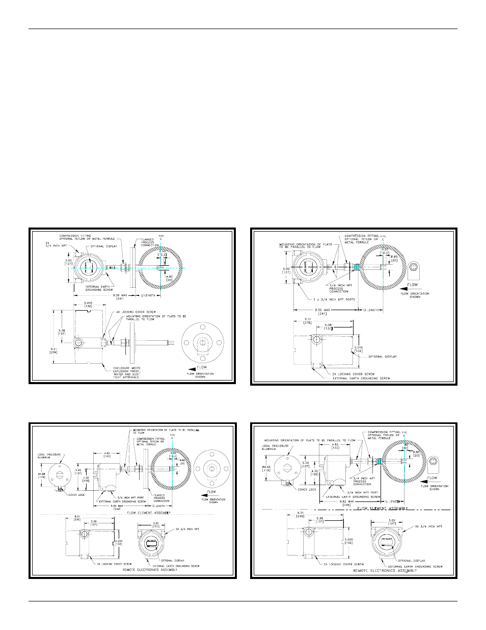
Below are the most common instrument mounting options shown in a typical customer process. See the Installation Section in the
ST98 Manual, Document Number 06EN003291 for more details.
Step 2.
Flow Element Installation
Flanged Integral Instrument (Cylindrical Enclosure)
NPT Integral Instrument (Cylindrical Enclosure)
Flanged Remote Instrument (Cylindrical Enclosure)
NPT Remote Instrument (Cylindrical Enclosure)