Electrical data – Burkert Type 8020 User Manual
Page 5
16
downstream distances respected, appropriate pipe dimensions
Tab. 2:
Dimension H [mm] of the 8020 depending on
the DN of fitting S020
H
T fitting
Saddle
Spigot, in
plastic
Welding
tab with
radius, in
stainless
steel
DN20
153.5
DN25
153.5
DN32
157.0
DN40
161.0
DN50
167.0
191.5
162.5
DN65
167.0
190.5
172.5
167.0
DN80
194.5
177.5
173.0
DN100
199.5
184.0
183.5
English
17
H
T fitting
Saddle
Spigot, in
plastic
Welding
tab with
radius, in
stainless
steel
DN110
195.5
DN125
202.5
194.5
DN150
212.5
230.0
205.5
DN180
236.5
DN200
248.5
251.0
226.0
DN250
269.0
286.0
DN300
280.5
305.5
DN350
294.0
317.5
DN400
308.5
English
17
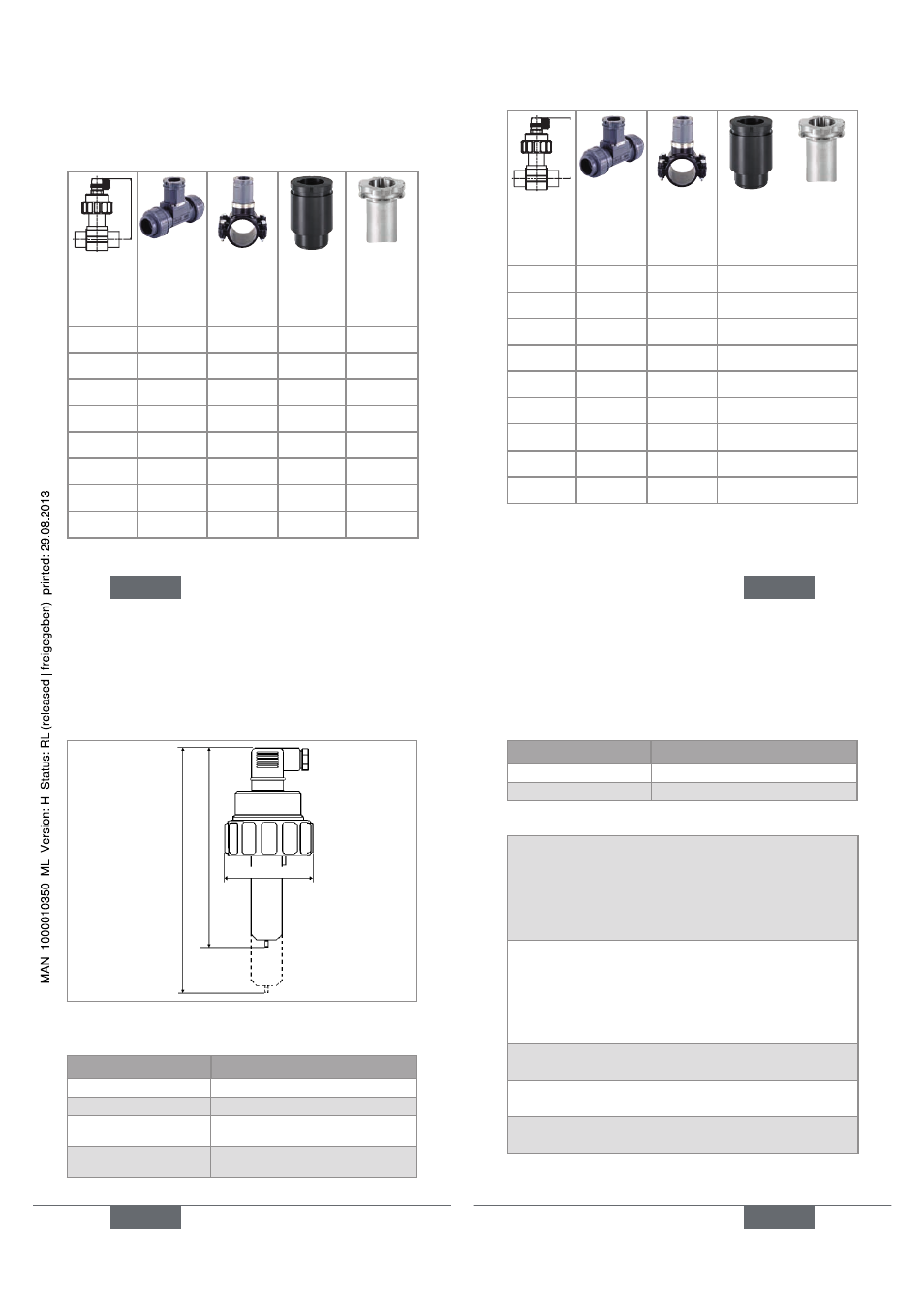
18
191 mm
153 mm
75 mm
Fig. 1: Dimensions [mm] of the flowmeter 8020
materials
Part
Material
Housing
PE
Nut
PC
Female connector type
2508 / screw / seal
PA / Stainless steel / NBR
Frame of the flow sensor
and paddle wheel
PVDF
English
19
Part
Material
Axis and bearings
Ceramic
Gasket
FKM (EPDM optional)
electrical data
Supply voltage
• Hall version
• Hall Low Power
version
• 12-36 V DC, filtered and
regulated
• 12-36 V DC, via transmitter the
device is connected to
Current
consumption
• Hall version
• Hall Low Power
version
• 50 mA max.
• 0,8 mA max.
Protection against
polarity reversal
yes
Protection against
spike voltages
yes
Protection against
short circuits
yes
English
19