Electrical connection of safety block, Connection diagram – Burkert Type 3005 User Manual
Page 34
34
9.3.
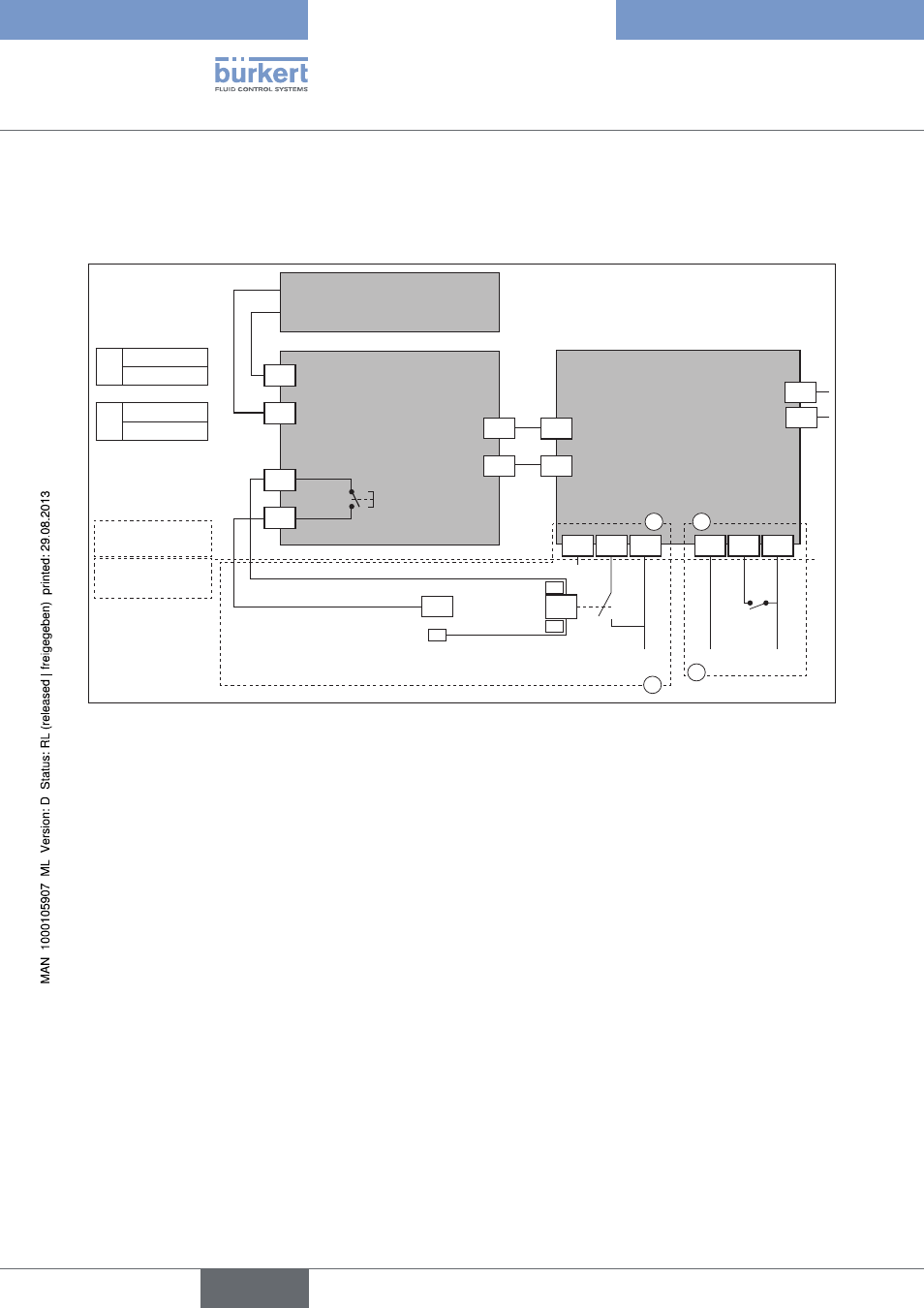
electrical connection of safety block
9.3.1.
connection diagram
65
F+
E-
66
17
18
17
18
battery block
control and power supply card
F+
Wire colour
red
E-
Wire colour
black
Load state
feedback
Loaded battery: closed
contact
1
2
3
1
2
3
D1
D2
Open
N
Ph
A
A
Ph
Open
KM1
N
A1
A2
N
24 V
AC/DC
B
B
100V-240V 50/60 hz (100V-350V Dc)
15V-30V 50/60 hz (12V-48V Dc)
On / Off Mode
KM1 - Customer
contactor switch
Suggestet customer
wiring
Actuator
wiring
Total security mode
safety block
Figure 27:
Connection diagram of emergency reset
Configuration A or B
A - standard mode: If the actuator is controlled with a programmable controller, the feedback of the charge state
can be connected to it.
B - mode - increased safety (if the feedback relay is used, terminals 65 and 66): The actuator does not actuate
the valve unless the safety block is loaded.
Option:Rotaryactuatorswith
emergencycurrentmodel
English
Type 3005
- Type 0125 (15 pages)
- Type 0121 (4 pages)
- Type 0330 (2 pages)
- Type 0331 (4 pages)
- Type 6012 (4 pages)
- Type 0127 (18 pages)
- Type 0131 (5 pages)
- Type 0141 (5 pages)
- Type 0142 (12 pages)
- Type 0145 (3 pages)
- Type 0174 (5 pages)
- Type 0212 (2 pages)
- Type 0211 (5 pages)
- Type 0212-B (18 pages)
- Type 0250 (64 pages)
- Type 0253 (2 pages)
- Type 0255 (15 pages)
- Type 0355 (2 pages)
- Type 0255 (2 pages)
- Type 8006 (34 pages)
- Type 8640 (2 pages)
- Type 8640 (55 pages)
- Type 8640 (119 pages)
- Type 0256 (15 pages)
- Type 0256 (2 pages)
- Type 0258 (72 pages)
- Type 0262 (5 pages)
- Type 0273 (6 pages)
- Type 0280 (5 pages)
- Type 0280 (2 pages)
- Type 0280 (12 pages)
- Type 0281 (2 pages)
- Type 0282 (2 pages)
- Type 0283 (2 pages)
- Type 0286 (4 pages)
- Type 0287 (15 pages)
- Type 0290 (2 pages)
- Type 0290 (14 pages)
- Type 0293 (18 pages)
- Type 0300 (6 pages)
- Type 0301 (6 pages)
- Type 0311 (2 pages)
- Type 0312 (6 pages)
- Type 6518 (57 pages)
- Type 6519 (3 pages)