Version with analog signal input – Burkert Type 3005 User Manual
Page 27
27
Installation
The limit switch contacts are actuated via two cams no. 13 (see “Figure 1”, page 10 and “Figure 2”, page 11).
• The white cam is used to record the opening process (FC1).
• The black cam is used to record the closing process (FC2).
procedure:
→
Connect cable to the terminal strip 12 (see “Figure 1”, page 10 and “Figure 2”, page 11) according to the
schematic (see “Figure 19”).
8.2.3.
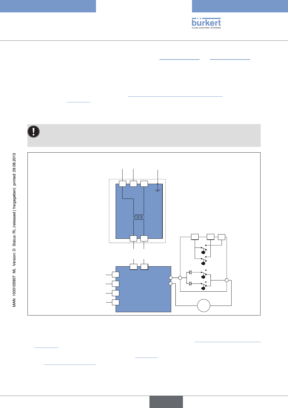
Version with analog signal input
The power supply voltage of the actuator is 15-30 V AC (12-48 V DC) or 100-240 V AC
(100-350 V DC).
Always observe the specifications on the type label!
0 – 20 mA / 4 – 20 mA / 0 – 10 V
T/E
FC2
FC1
FCF
FC0
4-6
5
7
=
C
B
D
D
A
C
2
17
18
18
17
N
-
Ph
+
N
-
Ph
+
3
1
16
15
14
13
+
-
-
+
Motor
Feedback
Power supply
100-240 V AC
(100-350 V DC)
or
15-30 V AC
(12-48 V DC)
Input
Feedback
Power supply
24 V DC
Figure 20:
Circuit diagram
procedure:
→
Loosen left cable gland 15 and feed through the cable to be connected (see “Figure 1”, page 10 and “Figure
2”, page 11).
→
Connect cable according to the circuit diagram (see “Figure 20”) to the terminal strip Pos. 14 of the power supply card
(see “Figure 1” and “Figure 2”).
English
Type 3005