Burkert Type 3005 User Manual
Page 26
26
Installation
Auf
Zu
N
-
Ph
+
1
2
3
T/E
Auf
N
-
Ph
+
3
2
1
T/E
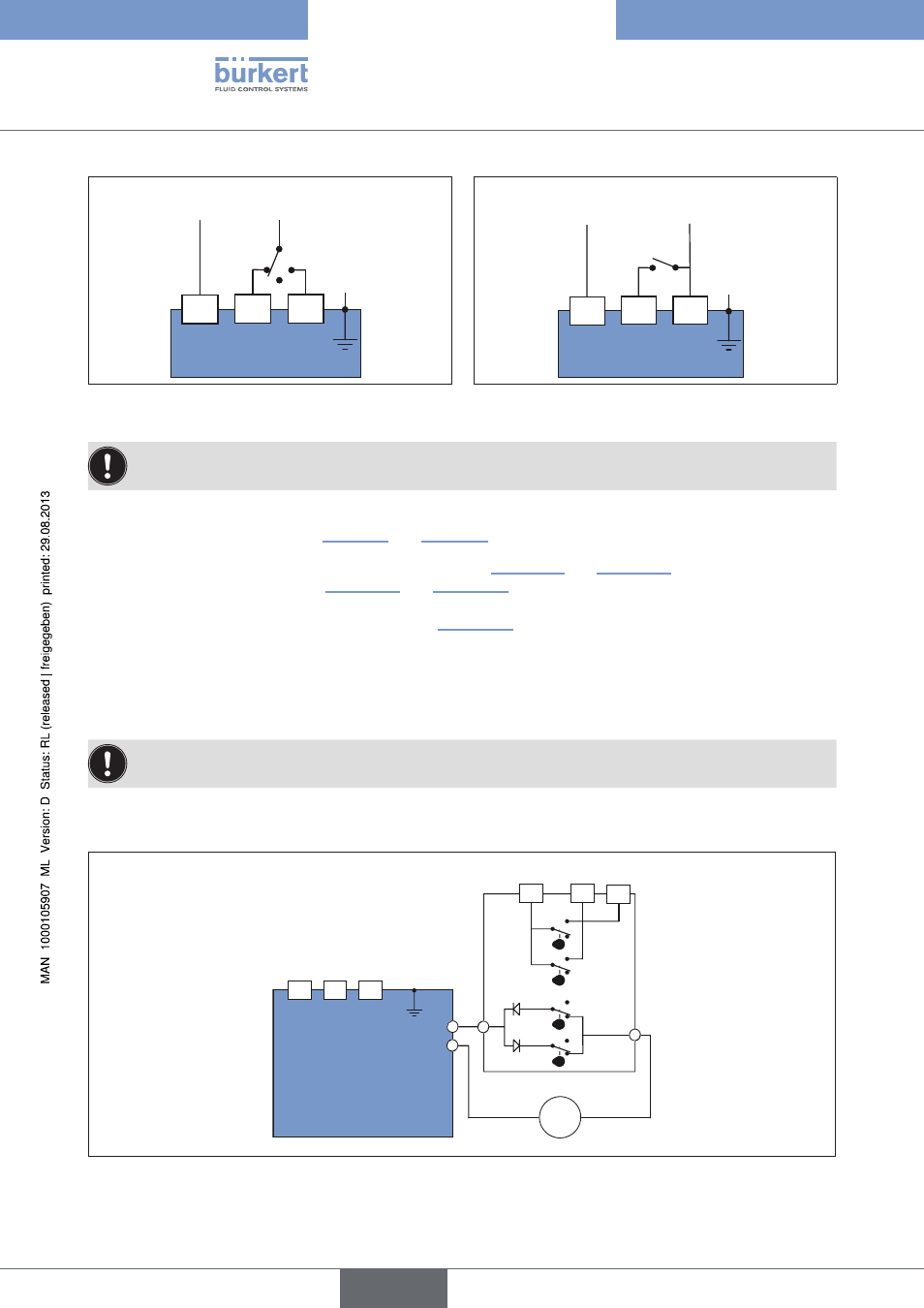
Figure 17:
Three points mode
Figure 18:
Open / Closed mode / Emergency current
model
If voltage is applied simultaneously to terminals 2 and 3, terminal 2 is the leading one and the actuator
moves to the OPEN position.
procedure:
→
→
Connect cable according to the required control type (see “Figure 17” and “Figure 18”) to the terminal strip Pos.
B of the power supply card (see “Figure 15” and “Figure 16”).
Operating principle for Open / closed mode (see “Figure 18”) :
• Switch open = actuator closes
• Switch closed = actuator opens
connecting feedback
The limit switches for the feedback are suitable for a maximum voltage of 250 V AC/DC – 5 A.
The rotary actuator features two additional limit switch contacts which are supplied by the factory in an open position.
These can be used for the feedback of the rotary actuator.
2
3
1
FC2
FC1
FCF
FC0
4-6
5
7
=
C
C
A
B
D
D
T/E
Motor
Feedback
Power supply and control
Figure 19:
Internal wiring of actuator
English
Type 3005