Hardware – Burkert Type 7616 User Manual
Page 18
18
Dosingsystem(Optional)
hardware
9.4.
Control (1)
Valves (2)
GND
+12 – +24 V DC
(according to the
nominal voltage of the valves)
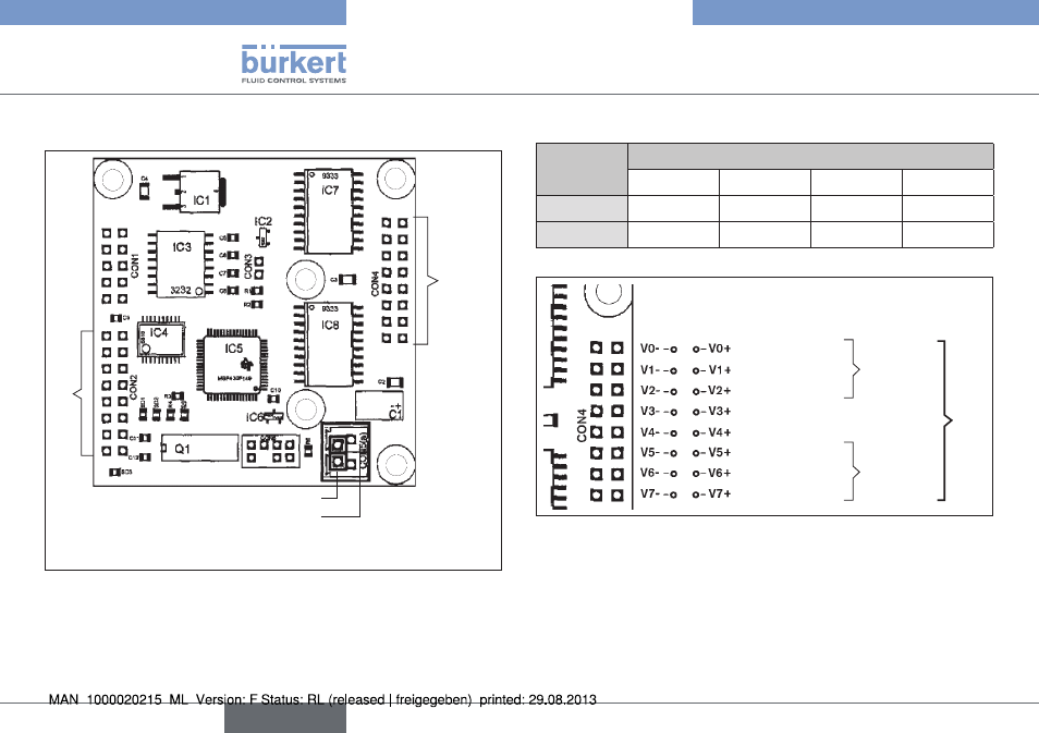
Overview, hardware allocation
Fig. 8:
hardware allocation of the valve outputs (2) to the dosing units.
dosing
unit
Valve outputs
V0- / V0+
V1- / V1+
V2- / V2+
V3- / V3+
1
P11
P12
P13
-
2
P21
P22
P23
-
Inlet valve
Pump valve
Outlet valve
Dosing
unit 1
Inlet valve
Pump valve
Outlet valve
Valves (2)
Dosing
unit 2
Hardware allocation: Valves / Dosing unit
Fig. 9:
english
Type 7616