Fluid connections 7.4. installation – Burkert Type 7616 User Manual
Page 11
11
Installation
fluid connections
7.3.
Warning!
Burns, chemical burns through leaking medium.
Prior to the use of aggressive media, the resistance of the
•
media-wetted parts must be checked. If you are unsure, please
contact your Bürkert Sales Centre.
Connect the fluid connections according to required
→
flow direction (see chart and diagram "Fluid connections").
flow direction
port 1
port 2
Forward
Input
Output
Reverse
Output
Input
Port 1
Port 2
Fluid connections
Fig. 2:
Mount the hose connection as shown in the illustration.
→
Ferrule
Fitting
Hose
Structure UNF
Fig. 3:
¼ – 28 for fluid connection
installation
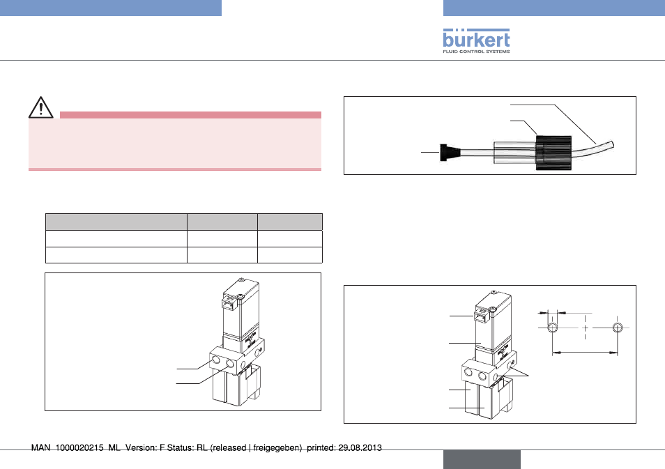
7.4.
Installation position: any position
Fasten the device.
→
Use the respective bores for M3 screws
(see figure "Installation").
M 3
Bores forfastening
Bore hole illustration:
Rectangular connector
Valve 3
Valve 2
Valve 1
20.5
Installation
Fig. 4:
english
Type 7616