Burkert Type 8681 User Manual
Page 9
32
Process data
2 static input assemblies
(Input: from the control head to the
DeviceNet Master/Scanner)
1 static output assembly
Inputs
3 discrete feedback signals of the posi-
tion measuring system (pos. S1 - S3)
1 discrete feedback signal of the
external initiators (S4)
1 analog position signal in mm
Supply via DeviceNet string
(11 to 25 V DC)
Switch level high signal
5 V
Switch level low signal
1,5 V
Outputs
3 solenoid valves
Power consumption
from the bus:
max. 5 W, (3 valves with each 0,8 W)
Length of the Bus line
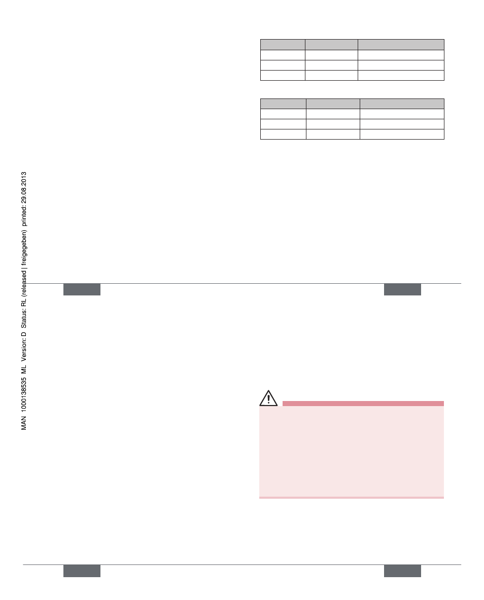
11.3.
The maximum total line length (sum of trunk lines and drop
lines) of a network depends on the baud rate.
The maximum total line length (according to DeviceNet
specifi cation) is for:
english
33
Baud rate
Thick Cable
Thin Cable
125
500 m
100 m
250
250 m
100 m
500
100 m
100 m
The maximum drop line length is for:
Baud rate
Drop Line
Sum (in Network)
125
6 m
156 m
250
6 m
78 m
500
6 m
39 m
Electrical Data
11.4.
Electrical power supply:
11 to 25 V DC (according to
specifi
cation)
Max. power consumption: 200 mA at 24 V DC
Input / proximity switches (external initiator: S4 in):
Power supply:
via DeviceNet power
supply - 10 %
Current carrying capacity
sensor power supply:
max. 30 mA
Short-circuit protection
Design:
DC 2- and 3-conductor,
NO contact, PNP output
english
34
Input current 1 signal:
I
Sensor
> 6.5 mA, limited
internally to 10 mA
Input voltage 1 signal:
U
Sensor
> 10 V
Input current 0 signal:
I
Sensor
< 4 mA
Input voltage 0 signal:
U
sensor
< 5 V
Inputs (from master perspective) / binary or analog
feedback signals:
The recovery of the 3 valve positions reported back binarily
or of the analog position signalis described in the manual,
chapter “Position Mesuring System”.
Outputs (from master perspective) / solenoid valves:
max. switching capacity 1.0 W
typ. continuous output
0.8 W
Output reduction
integrated via DeviceNet
interface
electronics
pull-in current
120 mA typ. / 200 ms
(3
valves)
Holding current
100 mA typ. at 24 V DC
(3
valves)
Operating mode
Long-term operation
(100 % operation)
Valve types
6524
Central display of the switching states:
Power consumption from
DeviceNet at 24 V DC
42 mA with 24 V DC power
english
35
supply per illuminated display
shown; Color switching see
in the manual, chapter “LED -
Color
Assignments”
Electrical Installation (DVN)
11.5.
WARNING!
Risk of injury due to electrical shock!
Before reaching into the system (except for the
•
Teach-In procedure in a non-explosive atmosphere)
switch off the power supply and secure it to prevent
restarting!
Observe applicable accident prevention and safety
•
regulations for electrical equipment!
Risk of injury from improper installation!
Installation may be carried out by authorized techni-
•
cians only and with the appropriate tools!
No internal cabling work is required for any of the Devi-
ceNet designs.
However, you will require the correspondingly assembled
cable sets with the pin assignments described below:
english
Type 8681