Burkert Type 8681 User Manual
Page 10
36
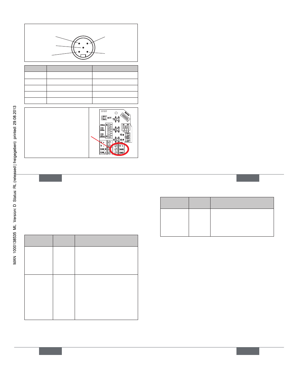
Pin 4: CAN_H
Pin 5: CAN_L
Pin 1: Drain
Pin 3: V–
Pin 2: V+
View of plug from the front onto the pins:
Pin
Signal Color
1
Drain
(shield)
2
V+
red
3
V-
black
4
CAN_H
white
5
CAN_L
blue
An external initiator can be
connected using the small
3-pin terminal strip - see
manual, chapter „Connection
of an external initiator“.
english
37
Network Topology
11.6.
When installing a DeviceNet system, ensure that the termi-
nating circuit of the data lines is correct. The circuit prevents
the occurrence of interference caused by signals refl ected
onto the data lines.
The trunk line must be terminated at both ends with
resistors of 120
Ω
and 1/4 W power loss (see the manual,
chapter „Network Topology of a DeviceNet System“).
Confi guring the Baud rate
11.7.
and DVN address
8 DIP switches are available for confi guration:
DIP switches 1 to 6
for DeviceNet address
•
(factory setting:
63, i.e. DIP 1 - 6: on)
DIP switches 7 to 8
for Baud rate
•
(factory setting:
125, i.e. DIP 7 + 8: off)
Further confi guring - see manual, chapter „Confi guring the
DeviceNet address / baud rate“
english
38
Confi guration of Process Data
11.8.
To transmit process data via an I/O connection, 2 static
input and 1 static output assembly can be selected, see
manual, chapter “Confi guration of Process Data”
„Address“ in the table describes the data attribute of the
assemblies for read access (class, instance, attributes).
Input-
Assemblies
Address
Format of the Data attribute
value 0: OFF / value 1: ON
S1…S4
(factory
setting)
4, 1, 3
Byte 0:
Bit 0: position S1
Bit 1: position S2
Bit 2: position S3
Bit 3: position S4
S1…S4 +
POS
(with POS:
current
position)
4, 2, 3
Byte 0:
Bit 0: position S1
Bit 1: position S2
Bit 2: position S3
Bit 3: position S4
Bit 4…7: not used
Byte 1:
POS in mm
„Address“ in the table describes the data attribute of the
assemblies for read access (class, instance, attributes).
english
39
Output-
Assembly
Address
Format of the Data attribute
value 0: OFF / value 1: ON
Solenoid
valve
SV 1 ... 3
4, 21, 3
Byte 0:
Bit 0: SV1
Bit 1: SV2
Bit 2: SV3
Bit 3…7: not used
Confi guration of the Safety
11.9.
Position of Solenoid Valves if
Bus Error
If the bus fails, the solenoid valve is switched to a program-
mable safety position (factory setting: the solenoid valve
is in the power-off-state) - for details see manual, chapter
„Confi guration of the device“.
The bus status LED „Network“ on the electronic module
specifi es the kind of error by color and blinking pattern - for
details see manual, chapter „Display of the Status LEDs in
the event of a bus error“).
english
Type 8681