Burkert Type 8681 User Manual
Page 6
20
Electrical Data
9.2.
Power supply:
12 ... 28 V DC, residual ripple 10 %
Power consumption:
(standby current):
30 mA at 24 V DC
Solenoid valves:
Power input per max. 0.8 W
solenoid valve:
(0.9 W during activation)
Operating mode: Long-term operation (100 %)
Central display of the
switching states:
42 mA with a power supply of
24 V DC per illuminated display;
Outputs/binary
feedback signals:
S1 out - S4 out
Design:
Normally open contact, PNP output
short-circuit-proof, with self-clocking
short-circuit
protection
Switchable
output current:
max. 100 mA per feedback signal
Option: Analog feedback signal:
Signal output:
S3 out (binary feedback signal
S3out not available)
Type:
Current source (4 to 20 mA)
english
21
Input / proximity switches (external initiator: S4 in):
Power supply:
Voltage present at control head - 10 %
Current carrying
capacity, sensor
power supply:
max. 90 mA;
short-circuit
protection
Design:
DC 2- and 3-conductor, NO or NC
(factory setting NO), PNP output
Valve control inputs (Y1 - Y3):
Signal level - active: U > 10 V, max. 24 V DC + 10 %
Electrical Installation
9.3.
(24 VDC)
WARNING!
Risk of injury due to electrical shock!
Before reaching into the system (except for the
•
Teach-In procedure in a non-explosive atmosphere)
switch off the power supply and secure it to prevent
restarting!
Observe applicable accident prevention and safety
•
regulations for electrical equipment!
Risk of injury from improper installation!
Installation may be carried out by authorized techni-
•
cians only and with the appropriate tools!
english
22
Cable glands:
Open the housing.
Assemble connection cables for signals and power
supply as well as for the external initiator.
Insert cables through the respective cable glands into
the interior of the housing.
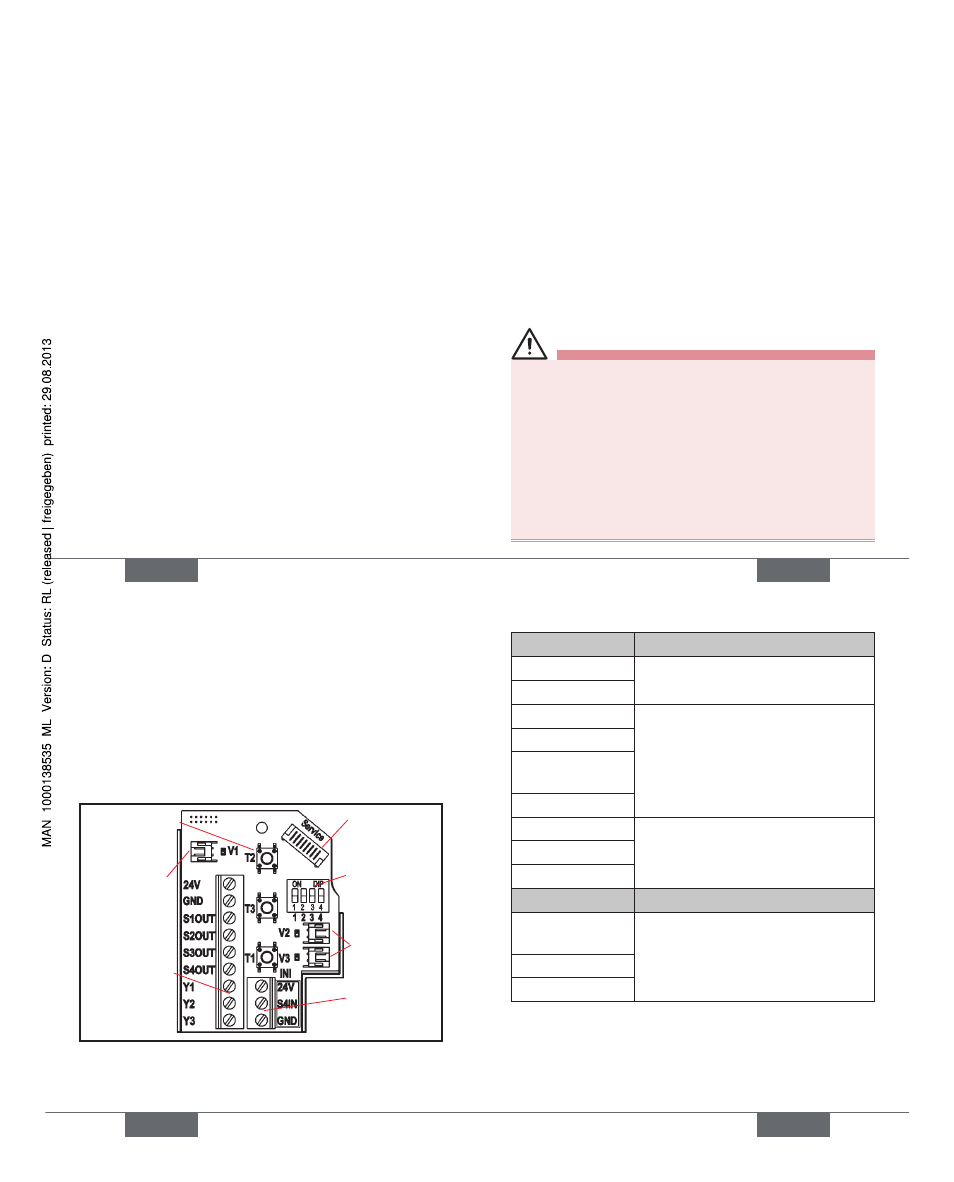
Secure the wires to the terminal strips according to the
pin assignments depicted in the fi gure.
Solenoid valve
connection
with status
LED for SV1
Terminal strip 1
Service
interface
DIP switches
for color
coding the
LED‘s
Terminal strip 2
(for external
initiator)
Teach-In-
buttons T1-3
SV-connections
with status LED
for SV2, 3
english
23
Terminal strip 1
Confi guration
24 V
Power supply 24 V
GND
GND
S1 OUT
Output position 1
S2 OUT
Output position 2
S3 OUT
Output position 3
(Option: analog signal)
S4 OUT
Output external initiator
Y1
Input solenoid valve 1
Y2
Input solenoid valve 2
Y3
Input solenoid valve 3
Terminal strip 2
Confi guration
24 V
Power supply 24 V for external
initiator
S4 IN
Input external initiator
GND
GND external initiator
Close the housing
.
Ensure IP protection
(dummy plugs)!
english
Type 8681