Burkert Type 8681 User Manual
Page 11
40
120 V AC - DESIGN
12.
Connection
12.1.
left connection:
1 x M16 x 1,5 cable gland for
power supply and signals
right connection:
1 x M16 x 1,5 cable gland for
external initiator
Electrical Data
12.2.
Central power supply: 110 ... 130 V AC, 50/60 Hz
Power consumption
(stnd-by current):
10 mA at 120 V AC
Solenoid valves:
power
consumption
per solenoid valve:
max. 1,4 VA
(1,7 VA during activation)
power
consumption
per solenoid valve:
12 mA at 120 V AC
Operation mode:
Long-term operation (100 %)
english
41
Central display of the switching states:
13 mA with a power supply of
120 V AC per illuminated display
Outputs/binary
feedback signals:
S1out - S3out
Design:
NO contact, L switching,
short-circuit protection via auto-
matically resetting fuse
switchable output
current:
max. 50 mA per feedback signal
Output voltage
- active:
(operating voltage - 2 V)
- inactive:
max. 1 V in unloaded state
Feedback signal output: S4 out is directly connected to
S4
in
Input / proximity switches (external initiator: S4 in):
Power supply:
voltage present at control head
U
Nominal
= 120 V AC, 50/60 Hz
Current carrying capacity,
sensor power supply:
max. 0.7 A
Short-circuit
protection
Design:
DC 2- and 3-conductor,
NO contact, L-switching
input current 1-Signal:
I
Sensor
< 2 mA
english
42
Valve control inputs (Y1 - Y3):
Signal level - active:
U > 60 V AC
Signal level - inactive:
U < 20 V AC
Impedance:
> 40 kOhm
Electrical Installation
12.3.
WARNING!
Risk of injury due to electrical shock (120 V AC)!
When setting the position measuring system
•
(Teach-In), do not contact any live components!
Before reaching into the system (except for the
•
Teach-In procedure in a non-explosive atmosphere)
switch off the power supply and secure it to prevent
restarting
Observe applicable accident prevention and safety
•
regulations for electrical equipment!
Risk of injury from improper installation!
the
•
PE connection must be connected!
Installation may be carried out by authorized techni-
•
cians only and with the appropriate tools!
english
43
Cable gland:
Open the housing.
Assemble connection cables for signals and power
supply as well as for the external initiator.
Insert cables through the respective cable glands into
the interior of the housing.
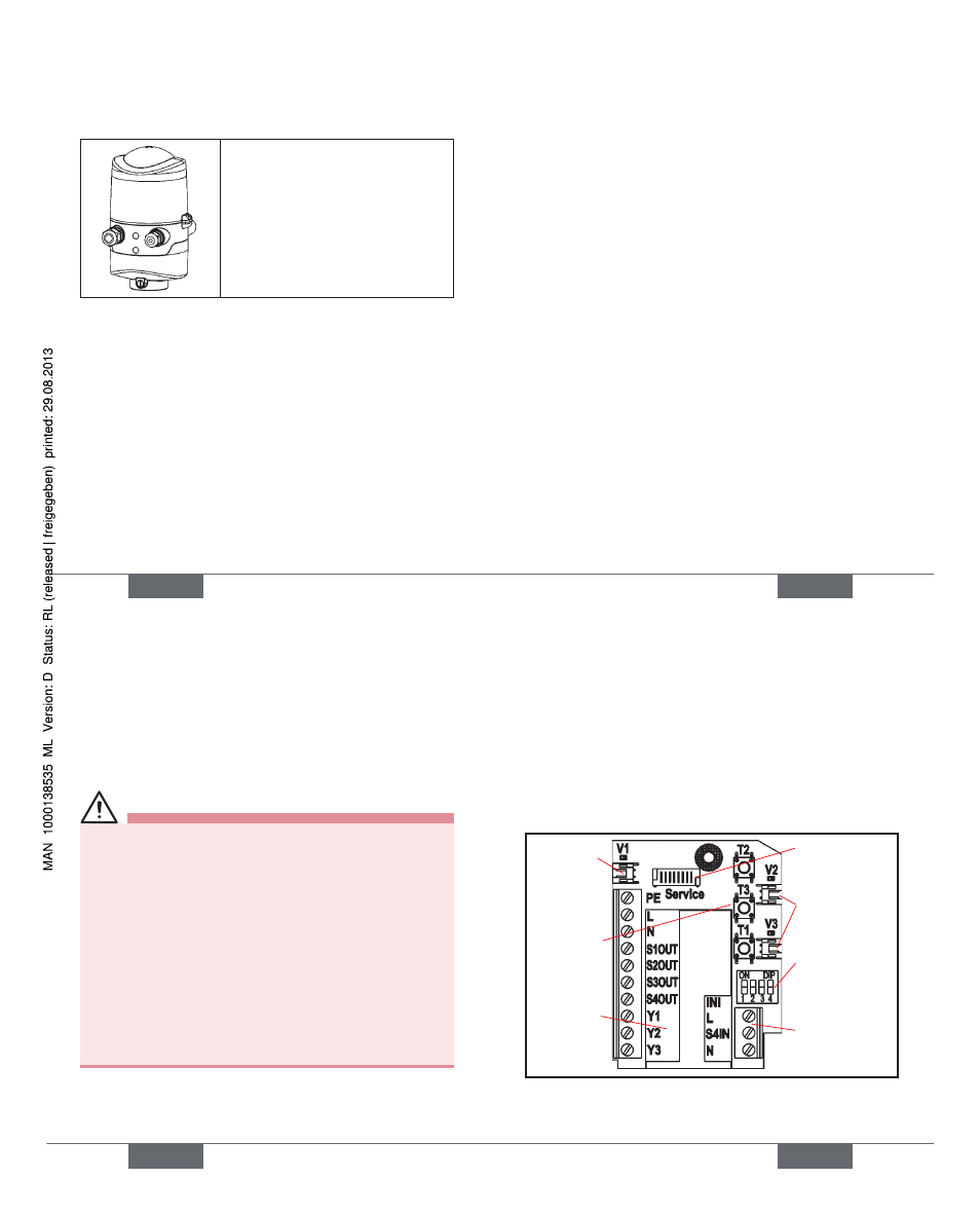
Connect the wires to the connection terminals
according to the pin assignment described in the
fi gure. Fix them.
connection
for valve 1
with status
LED
terminal
strip 1
service
interface
DIP-switches
for color
coding the
LED‘s
terminal strip 2
(external
initiator)
Teach-In-
buttons
T1-3
connections for
valve 2, 3 with
status LED
english
Type 8681