Burkert Type 8681 User Manual
Page 8
28
Current carrying capacity,
sensor power supply: max. 30 mA;
short-circuit
protection
Design:
DC 2- and 3-conductor, NO or
NC (factory setting NO), PNP
output
Inputs (from master
perspective):
3 binary feedback signals and
external initiator
Outputs (from master
perspective):
0 to 3 solenoid valves
Switching capacity: max. 0.8 W via AS interface
Pull-in current:
30 mA or 0.9 W / 200 ms
Operating mode:
Long-term operation (100 %)
Central display of the switching states:
Power consumption: max. 33 mA or 1 W per illumi-
nated display (at 30.5 V AS-
interface
voltage)
Power supply via AS interface bus:
Power consumption
from AS interface:
max. 200 mA (incl. external
initiator with 30 mA)
Integrated short-circuit protection
english
29
External Power Supply:
Ext. power supply:
19.2 V DC to 31.6 V DC
Max. power consumption
from external power supply:
110 mA at 24 V DC
Integrated short-circuit protection
Electrical Installation (AS-i)
10.5.
WARNING!
Risk of injury due to electrical shock!
Before reaching into the system (except for the
•
Teach-In procedure in a non-explosive atmosphere)
switch off the power supply and secure it to prevent
restarting!
Observe applicable accident prevention and safety
•
regulations for electrical equipment!
Risk of injury from improper installation!
Installation may be carried out by authorized techni-
•
cians only and with the appropriate tools!
Internal cabling work is not required for any of the AS Interface
designs with multi-pole connection. However, you will require
the correspondingly assembled cable sets with the following
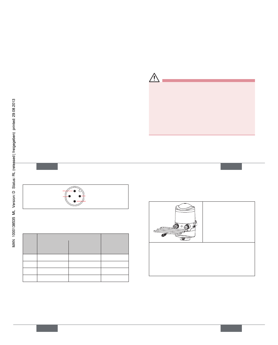
pin assignments.
english
30
Pin 2
Pin 3
Pin 1
Pin 4
Likewise, the jumpers on the electronics module must be set
correspondingly (power supply via AS-i or externally) - see
page 27 .
Power supply
Pin
(via AS-i)
Confi guration
(externally)
Confi guration
Color
1
AS-i+
AS-i+
brown
2
not used
GND
white
3
AS-i-
AS-i-
blue
4
not used
24 V+
black
An external initiator can be connected using the small
3-pin terminal strip 2 - see manual, chapter „Connection of
an external initiator“.
english
31
11.
DEVICENET- DESIGN
Connection
11.1.
left connection:
1 x M16 x 1,5 cable gland with Multi-pole connection
(M12 plug according to IEC 61076-2-101, 5-pole) on a
cable of 80 cm length
right connection:
1 x M16 x 1,5 cable gland for external initiator
DeviceNet Specifi cation
11.2.
EDS fi le
8681.EDS
Icons 8681.ICO
Baud rate
Factory setting: 125 kBit/s
Address
Factory setting: 63
english
Type 8681