Burkert Type 6606 User Manual
Page 7
24
note!
If the tightening torque is too great, the device may
be damaged!
Observe the maximum tightening torque of the screws!
•
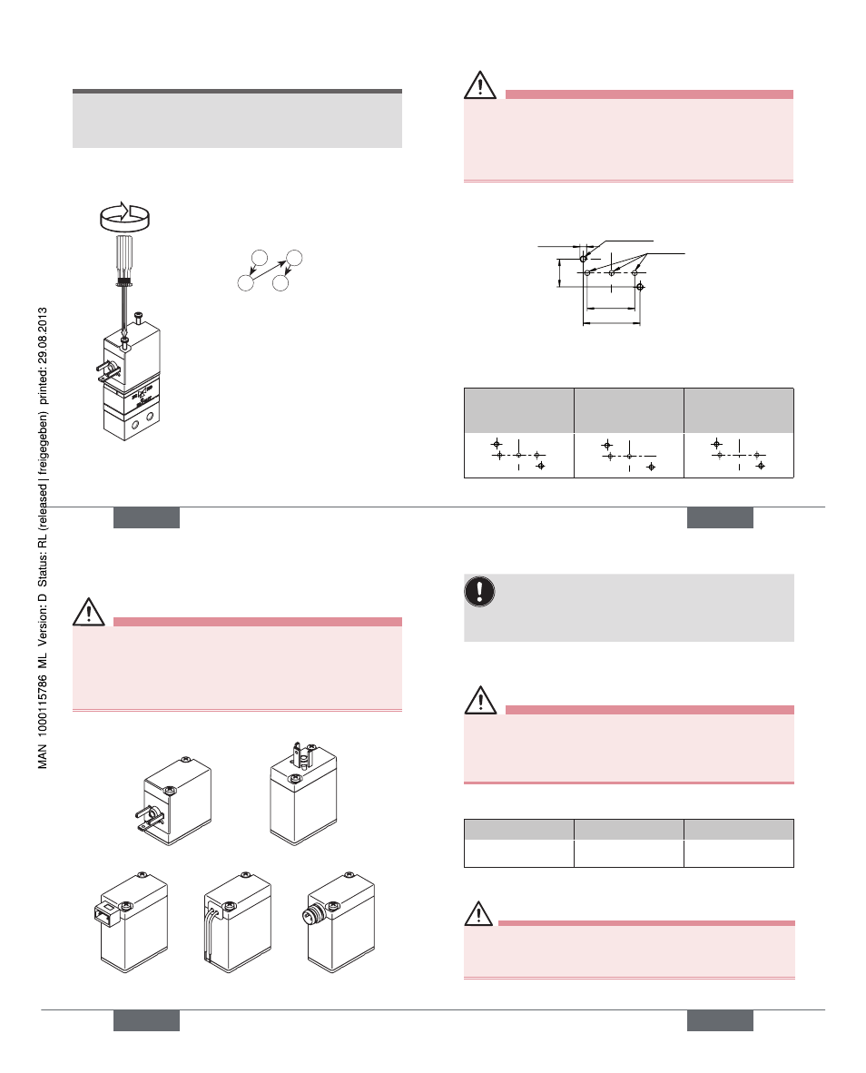
Attach valve to manifold:
→
Screw in screws at 0.3 ± 0.05 Nm.
Tighten screws alternately, in two
steps:
1st step:
Tightening torque 0.1 ± 0.05 Nm
2nd step:
Tightening torque 0.2 ± 0.05 Nm
1
2
3
4
1st step
2nd step
0.1 ± 0.05 Nm 0.2 ± 0.05 Nm
Attach coil to body.
→
english
25
Danger!
Risk of electric shock if the protective conductor
function is defective!
After installing the coil, check the functionality of the
•
protective conductor (see chapter entitled “
8.3. Elec-
trical Installation”).
Dimensional drawing for manifold:
NO
IN/OUT
NC
M2.5
min. 7.5 deep
max. ø2.5
18
21.5
10.5
Arrangement of the bores:
3-way
2-way PVDF and
virtually dead
storage version
2-way PEEK /
PPS
english
25
26
8.3. electrical installation
Danger!
Risk of injury due to electrical shock!
Before reaching into the device or the equipment,
•
switch
off the power supply and secure to prevent reactivation!
Observe applicable accident prevention and safety
•
regulations for electrical equipment!
Types of electrical connections:
Rectangular connector Flying leads
Circular connector
Connection at side
Connection above
english
27
To ensure functional reliability, operate the valve with
the coil installed ex works only!
Note the voltage and current type as specified on
the type plate. Voltage tolerance ±10 %
Valves with flange body:
Danger!
Risk of electric shock if the protective conductor
function is defective!
After installing the coil, check the functionality of the
•
protective conductor.
Check functionality of the protective conductor.
→
Resistance
Test voltage
Test current
max. 0.1 Ω
12 V
1 A
Connection to cable plug:
Danger!
Risk of electric shock if protective conductor not
connected!
Always connect protective conductor!
•
Earthing connection (if fitted): Middle spade connection
english
27
Type 6126 / 6606