Burkert Type 2712 User Manual
Page 3
5
→
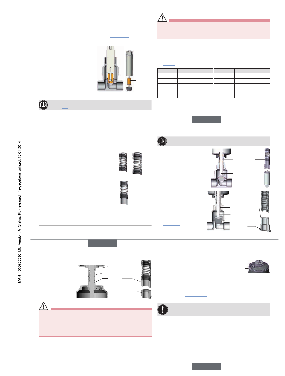
Support control cone on the cylindrical part with the aid of a prism or
something similar.
→
Put on dowel pin and carefully knock in with a hammer.
→
Position the dowel pin in the center of the spindle axis.
For mounting actuator on valve body see Chapter “3.4”, page 9.
3.2.1 replacing valve seat
→
Remove actuator (see Chapter
“3.1”)
→
Select a suitable tool insert and
screw it into the installation tool.
→
Unscrew the old valve seat using the
installation tool and a wrench.
→
Clean the thread of the body and the
sealing surface with compressed air.
Installation
tool
Tool insert
Valve seat
→
Place the new valve seat on the installation tool.
The installation tool is available from your Bürkert sales office (see
Chapter “4”).
Warning!
Unsuitable lubricant may contaminate the medium.
In oxygen applications there is a risk of explosion.
▶ Only use approved lubricants for specific applications, such as oxygen or
analytical applications.
→
Grease the valve seat thread with stainless steel lubricant
(e.g. with Klüber paste UH1 96-402 from Klüber).
→
Manually screw the fitted valve seat into the body thread.
→
Screw valve seat tight using torque wrench. Observe tightening torque (see
“Tab. 2”).
DN
Torque [Nm]
DN
Torque [Nm]
4-15
20 ± 3
50
120 ± 8
20
28 ± 3
65
150 +10
25
40 ± 5
80
180 +10
32
65 ± 5
100
220 +10
40
85 ± 8
Tab. 2:
Tightening torques for valve seat installation (valve seat coated)
For mounting actuator on valve body see Chapter “3.4”, page 9.
english
6
3.3 replacing packing gland seal set (only
Type 2301)
The seal set for the packing gland contains
SP10
SP14
SP10 / SP14
• 1 support ring
• 5 gaskets
• 2 or 3 pressure rings
1)
• 1 pressure spring
• 1 graphite seal
• Lubricant
SP22
• 1 support ring
• 7 gaskets
• 2 pressure rings
• 1 pressure spring
• 1 spacer
• 1 graphite seal
• Lubricant
Before the packing gland can be replaced, the actuator must be removed from
the valve body (see “3.1”, page 4) and the control cone removed (see “3.2”,
page 4).
1)
depending on the spindle diameter (10 or 14 mm)
Installation wrench or modified socket wrench is available from your
Bürkert sales office (see Chapter “4”).
PEEK spindle guide
Series-production status up to April
2012
→
Unscrew spindle guide with the
aid of the installation wrench
and an open-end wrench.
Installation
wrench
Packing gland
PEEK spindle
guide
Spindle
Packing gland tube
VA spindle guide
SP10/SP14
Series-production status from
April 2012
→
Unscrew spindle guide with
the aid of a modified socket
wrench and the open-end
wrench (see Chapter “Instal-
lation tools”).
Packing gland
VA spindle guide
Spindle
Packing gland tube
Hexagon
english
7
VA spindle guide SP22:
→
Unscrew spindle
guide with the aid of
an open-end wrench.
Packing gland
Spacer
Spindle
Packing gland tube
VA spindle guide
Warning!
Risk of injury from ejected parts!
When the spindle opening is exposed, the individual parts of the packing
gland are pressed out at an undefined speed when the control air connection
is pressurized.
▶ Before pressurizing with control air, safeguard the ambient area of the dis-
charge opening (e.g. place spindle on a firm base).
→
Press out packing gland:
For control function A and I:
Pressurize control air connection 1 with 6 ... 8 bar.
For control function B:
Pressurize control air connection 2 with 6 ... 8 bar.
1
2
Control air
connection
→
Grease the individual parts of the new packing gland with the supplied
lubricant.
→
Place the individual parts on the spindle in the specified direction and
sequence (see “Fig. 2”, page 8).
→
Push packing gland into the packing gland tube.
If the valve features a PEEK spindle guide (SP10 / SP14 series-pro-
duction status up to April 2012), we recommend replacing it with a
VA spindle guide. They are available from your Bürkert sales office.
→
Grease spindle guide thread with lubricant (Klüber paste UH1 96-402).
→
Screw spindle guide in again. Observe tightening torque
(see “Tab. 3”, page 8)!
english
Type 2301, 2712