Model sla7840 – Brooks Instrument SLA7840 User Manual
Page 30
4-6
Model SLA7840
Section 4 Maintenance
& Troubleshooting
Installation and Operation Manual
X-PR-SLA7800-RT-eng
Part Number: 541B048AAG
August, 2009
4-4 Orifice Sizing
The flow controller's orifice is factory-sized to a preselected gas, operating
pressure and flow range. Note that the orifice is marked with its size in
thousandths of an inch. When changing the gas operating pressure (inlet
or outlet), or flow range consult the factory for re-sizing information
4-5 Restrictor Sizing
The restrictor assembly is a ranging device for the sensor portion of the
controller. It creates a pressure drop which is linear with flow rate. This
diverts a sample quantity of the process gas flow through the sensor. Each
restrictor maintains a ratio of sensor flow to restrictor flow, however, the
total flow through each restrictor is different. Different restrictors (active
area) have different pressure drops and produce controllers with different
full scale flow rates. For a discussion of the interaction of the various parts
of the controller, you are urged to review Section 3-2, Theory of Operation.
If the restrictor assembly has been contaminated with foreign matter, the
pressure drop versus flow characteristics will be altered and it must be
cleaned or replaced. It may also be necessary to replace the restrictor
assembly when the mass flow controller is to be calibrated to a new flow
rate.
Restrictor assembly replacement should be performed only by trained
personnel. Consult Factory / Service center.
Restrictors
The Model SLA7840 remote transducer controller uses two types of
restrictor assemblies depending on full scale flowrate and expected service
conditions.
1. Wire mesh for Nitrogen equivalent flow rates above 3.4 slpm. These
restrictor assemblies are made from a cylinder of wire mesh and are
easily cleaned if they become contaminated in service.
2. Anti-Clog Laminar Flow Element (A.C.L.F.E.) - This type of restrictor
assembly is used for Nitrogen equivalent flow rates less than 3.4 slpm.
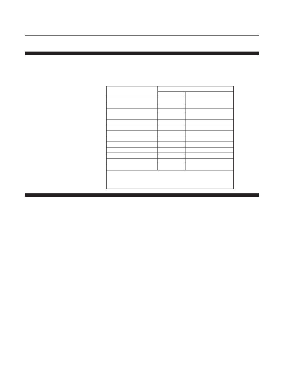
Table 4-2 Orifice Capacities
Orifice Size (inches)
Minimum Flow Rate (sccm)
0°C
(21.1°C)
0.0013
5.3
(5.7)
0.002
12.5
(13.5)
0.003
39.2
(42.2)
0.004
82.5
(88.9)
0.0055
190
(205)
0.007
374
(403)
0.010
748
(806)
0.014
1364
(1469)
0.020
2673
(2879)
0.032
6490
(6991)
0.048
12980
(13980)
0.062
22000
(2879)
0.078
31900
(34400)
Inlet Pressure = 10 psig
Outlet Pressure = 10 inches of water (0.4 psig) or less
Note: Flow Rate based on Nitrogen