Model sla7840 – Brooks Instrument SLA7840 User Manual
Page 15
2-3
Model SLA7840
Section 2 Installation
Installation and Operation Manual
X-PR-SLA7800-RT-eng
Part Number: 541B048AAG
August, 2009
2-7 Gas Connections
Standard inlet and outlet connections supplied on the Model SLA7840 are
1/4"(M) VCR or Downport surface mount per Semi 2787. Prior to
installation ensure all piping is clean and free from obstructions. Install
piping in such a manner that permits easy access to the instrument if
removal becomes necessary.
2-8 In-Line Filter
It is recommended that an in-line filter be installed upstream from the
mass flow controller to prevent the possibility of any foreign material
entering the flow sensor or control valve. The filtering element should be
replaced periodically or ultrasonically cleaned.
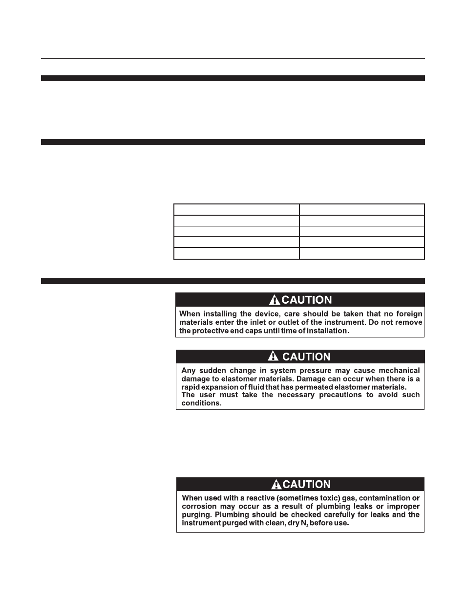
Table 2-1 Recommended Filter Size
Maximum Flow Rate
Recommended Filter
100 sccm
1 micron
500 sccm
2 microns
1 to 5 slpm
7 microns
10 to 30 slpm
15 microns
2-9 Installation
Recommended installation procedures:
a.
The Model SLA7840 RT should be located in a clean, dry
atmosphere relatively free from shock and vibration.
b.
Leave sufficient room for access to Self-zero function push-button.
c.
Install in such a manner that permits easy removal if the instrument
requires servicing.
d.
The Model SLA7840 RT can be installed in any position. However,
mounting in orientations other than the original factory calibration
(see calibration data sheet supplied with the instrument) can result in
a ±0.2% maximum full scale shift after rezeroing.