Model sla7840 – Brooks Instrument SLA7840 User Manual
Page 22
3-4
Model SLA7840
Section 3 Operation
Installation and Operation Manual
X-PR-SLA7800-RT-eng
Part Number: 541B048AAG
August, 2009
3-4 Analog Mode of Operation
A. Functional Description
The analog interface is consistent with other Brooks analog RTs. This
includes a 0-5 volt setpoint input, 0-5 volt flow signal output and Valve
Override input. Before operating the Model SLA7840, apply power and
warm-up the instrument for approximately one hour. After warm-up, apply
gas pressure then proceed by following the instructions in the following
sections.
B. Analog Setpoint
This input allows the user to establish the RT setpoint. The usable range of
this input is from 0 to 5.5 Vdc which corresponds to 0 to 110% of the RT
full scale flow rate. Setpoints below 50 mV will be treated as 0 volt
setpoints. For setpoints below 0 Vdc the RT behaves as if a 0 Vdc setpoint
is present. Setpoints above 5.5 Vdc will cause a setpoint of at least 110%
FS.
C. Analog Flow Signal
This output is used to indicate the flow signal. The range of this signal is
from -0.5 to 5.5 Vdc, with the range of 0 to 5.5 Vdc corresponding to a
calibrated flow signal of 0 to 110% of the full scale flow rate. A negative
flow signal indicates reverse flow through the device, but is NOT
calibrated. The analog flow signal is capable of resolving signals to 1.0 mV.
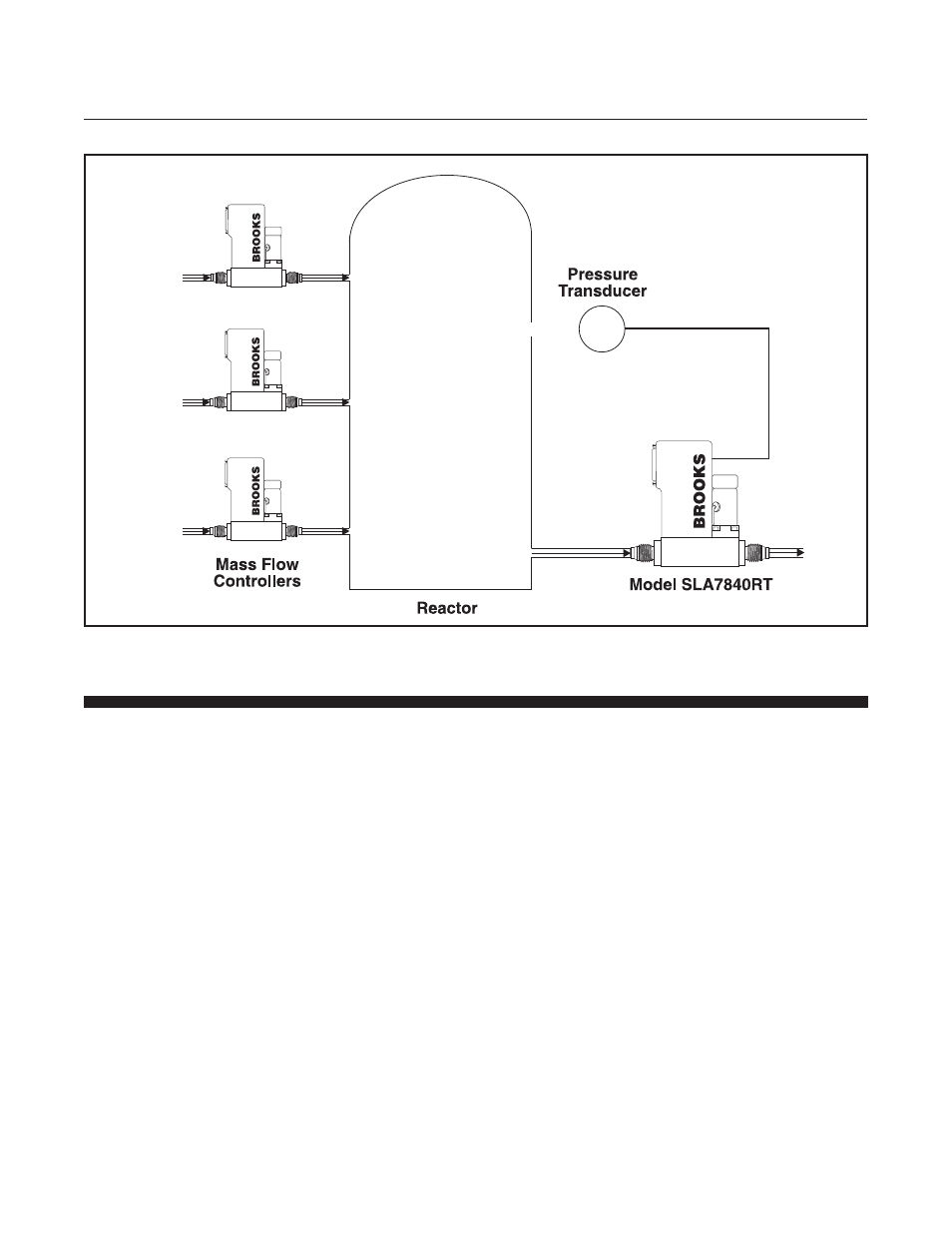
Figure 3-4 Typical Application of Upstream Controller