Model sla7840 – Brooks Instrument SLA7840 User Manual
Page 20
3-2
Model SLA7840
Section 3 Operation
Installation and Operation Manual
X-PR-SLA7800-RT-eng
Part Number: 541B048AAG
August, 2009
3-3 Theory of Operation for Remote Transducer
A user supplied pressure sensor, with a full scale output signal of 5 or
10 Vdc, monitors the pressure in a vessel or a feed or exhaust line from
the vessel. The control electronics in the Model SLA7840 compares the
pressure signal to a setpoint and acts to regulate the flow through the
integral solenoid control valve to stabilize the pressure at the setpoint. An
integral mass flow sensor identical in design to the Brooks Model SLA7840
provides a 5 Vdc full scale signal proportional to the flow through the
control valve. A system block diagram is shown in Figure 3-1.
The integration of mass flow sensor, control electronics and control valve
into one unit results in a compact size. The mounting dimensions are
comparable to a mass flow controller. Refer to Figure 3-2.
In the upstream pressure regulation mode shown in Figure 3-4, the
pressure controller is placed at the outlet of the pressure vessel. The
pressure in the process upstream of the controller will be constant
independent of downstream variation. Pressure control takes place at the
outlet side of the pressure vessel.
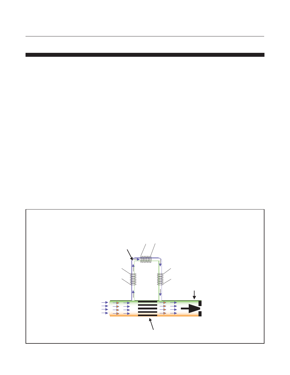
Figure 3-1 Flow Sensor Operational Diagram
Heater
TMF principle of measurement
Sensor
Sensor
Flow A
Flow A
Sensor
Flow A
Heater
Valve (if equipped)
T1
Upstream
Temperature
Sensor
T2
Downstream
Temperature
Sensor
Flow B
Flow B
Inlet
Flow A & B
Outlet
Flow A & B
Restrictor
Flow B
TMF principle of measurement
TMF principle of measurement