Bm oval series, Horizontal line – Brooks Instrument BM50 User Manual
Page 23
2-5
Section 2 Installation
Installation and Operation Manual
X-PD-BM-Ovals-eng
Part Number: 541B031AAG
January, 2009
BM Oval Series
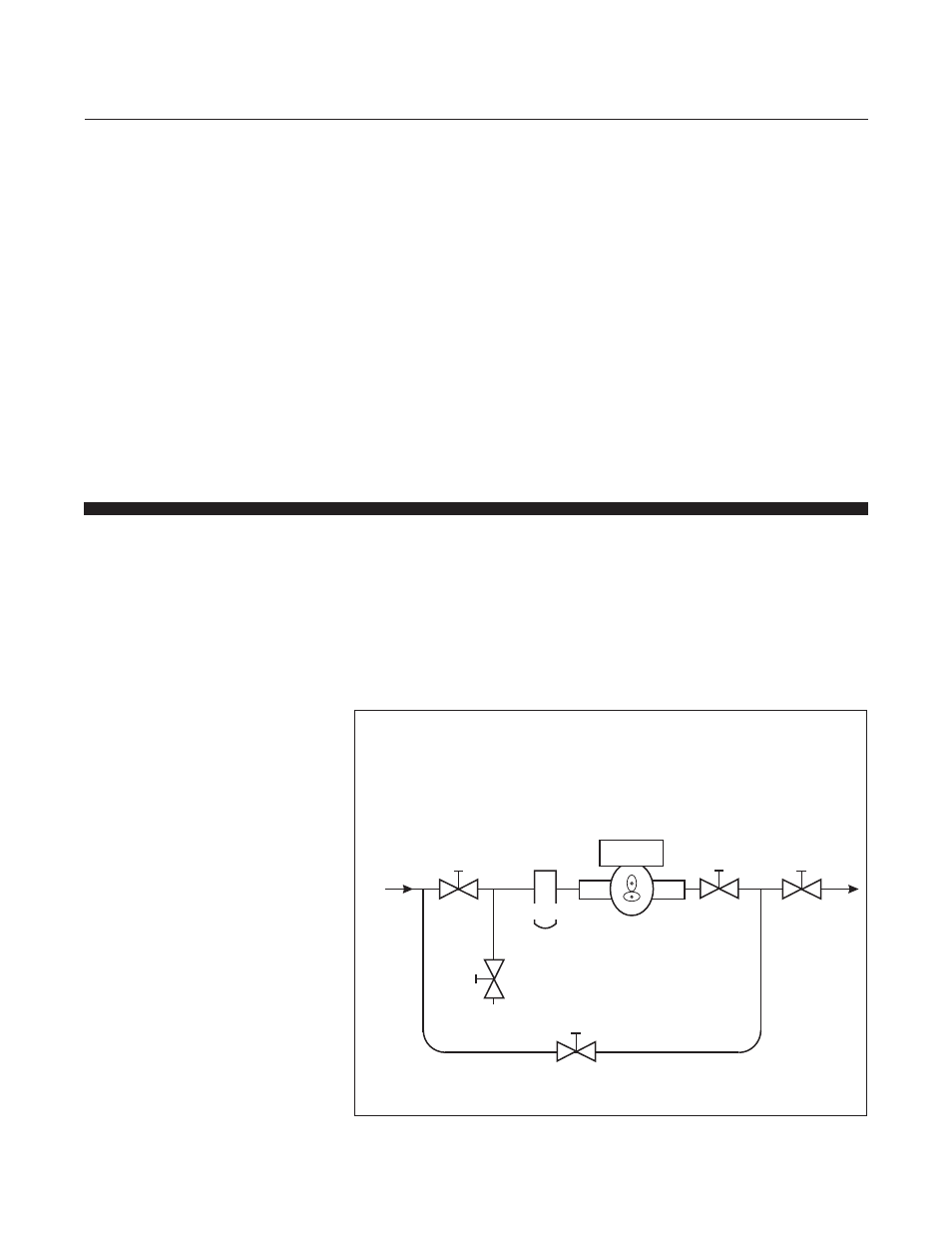
HORIZONTAL LINE
STRAINER
Drain
Valve
Bypass
Valve
Outlet
Valve
Control
Valve
Inlet
Valve
OVAL GEAR
FLOWMETER
Figures 2-5 Horizontal Installation.
(Refer to Table 2-1 for strainer size), ( See Figures 2-5 and 2-6).
4. Valves should be installed to facilitate removal of the flowmeter and
strainer, (See Figures 2-4 and 2-5).
5. Install the flowmeter on the discharge side of a pump whenever
possible.
6. Before installing the flowmeter, wash and clean the inside of the pipeline
with compressed air or steam. This is particularly important on new
pipelines.
7. Remove the protective covering from the flowmeter end connectors
before installation.
8. When making connection to the flowmeter make certain that no foreign
materials enter flowmeter body.
9. Ensure that the meter is installed so that the flow of the liquid is in the
direction of the arrows embossed on the meter body.
10. Refer to Figures 2-2, 2-3 or 2-4 for electrical connections.
2-7 Pre-Operation Procedures
1. After the flowmeter has been installed, slowly allow the liquid to flow in
bypass section of a horizontal installation or the main line of a vertical
installation. This will clear the line of any foreign particles.
2. Test the system for leaks.
3. Check the strainer for foreign material, after the first 50 gallons/200 liters
check periodically, particularly if the flow rate decreases.
NOTE: Foreign particles in the main line may cause damage to
the flowmeter.